Introduction
XBee is a wireless communication module that is built to the 802.15.4/ZigBee standard. These are popular wireless transceivers and are great for making a control network that spans over a range. They’re flexible, they send and receive data over a serial port, which means they’re compatible with both computers and microcontrollers (like Arduino). And they’re highly configurable (you can have meshed networks with dozens of XBees, or just a pair swapping data).
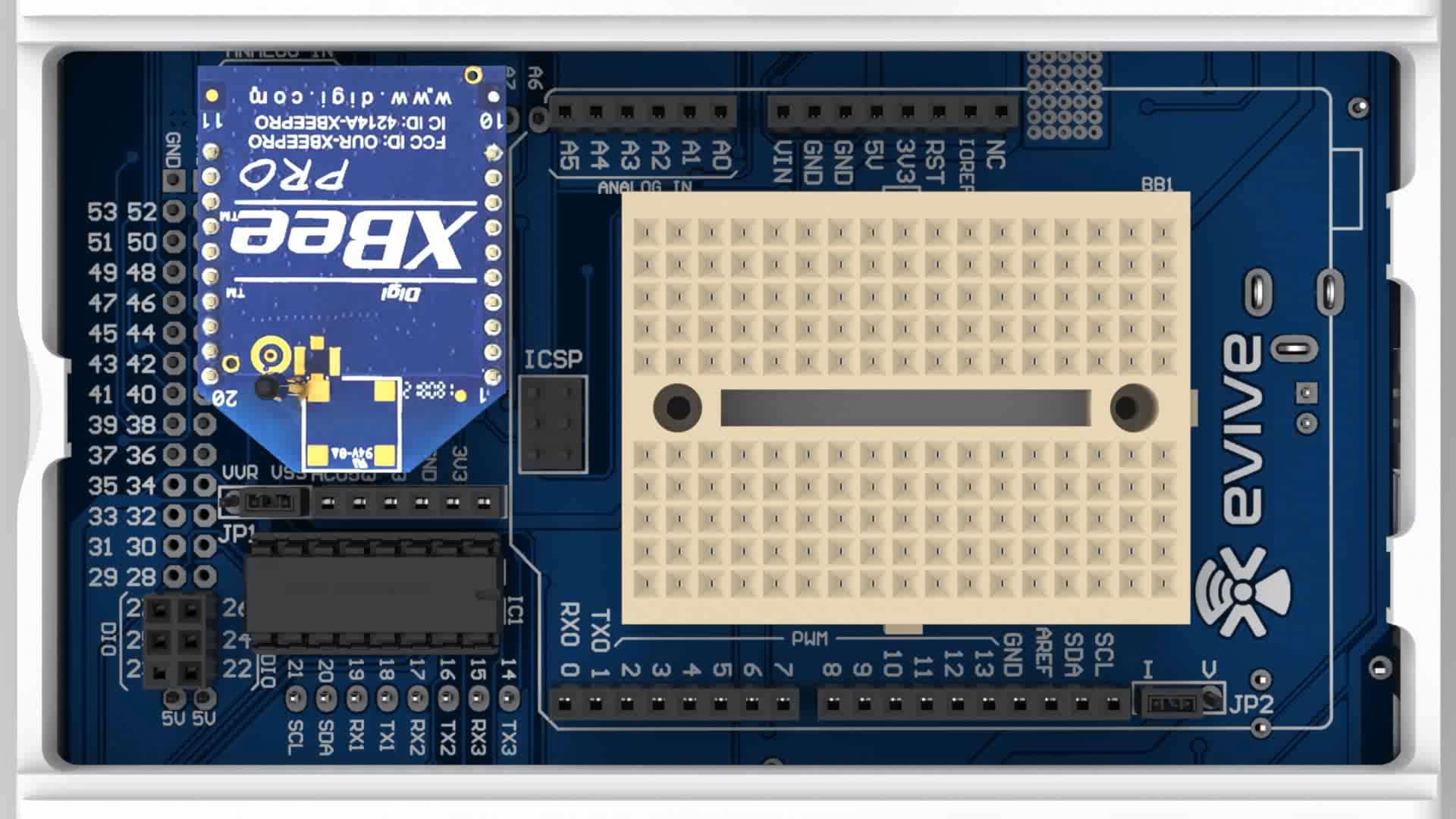
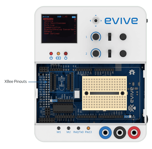
evive has dedicated XBee headers, which just requires you to connect the XBee Bluetooth module.
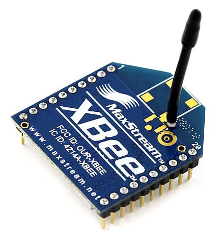
XBee module
XBees are only useful if you have a pair of them. In most cases, you’ll want a separate module to interface with the XBee but evive provides you with an inbuilt shield.
Features:
- Power output: 1 mW (+0 dBm)
- Indoor/Urban range: Up to 100 ft (30 m)
- Outdoor/RF line-of-sight range: Up to 300 ft (90 m)
- RF data rate: 250 Kbps
- Interface data rate: Up to 115.2 Kbps
- Operating frequency: 2.4 GHz
- Receiver sensitivity: -92 dBm
To make the communication through XBees, you have to first configure them. With the help of the X-CTU software, you can easily configure XBees, test connections, and pass data between your computer and remote XBees.
Starting With X-CTU
X-CTU is free software, provided by Digi which we use to configure and manage XBees and test XBee networks.
If you haven’t downloaded it already, head over to their website and download the latest release and follow their instructions to install the software.
Procedure to configure XBees
- Adding XBee’s
After initially opening X-CTU, you’ll be presented with a window like this: To add your XBee(s), click the “Add device” icon in the upper-left part of the window. - Select your communication port.
This window also allows you to specify more specific serial characteristics like baud rate, data bits, and stop bits. Assuming this is the first time you’ve used your XBee, you can leave those settings alone and click Finish.
A “Discovering radio modules…” window will briefly scroll by, after which you should be presented with the original window, but with an addition to the “Radio Modules” section on the left. - Click that new module and wait a few seconds as X-CTU reads the configuration settings of your XBee. You should then be presented with the entire configuration of your XBee.
As you can see by scrolling down the right half, there are a lot of configuration settings available. For now, verify that the configurable settings visible in the screenshot above match those of your XBee (channel=C, PAN ID=3332, DH=0, DL=0, MY=0). - Do It Again
To test communication between your XBee’s you’ll need to connect your second XBee to a computer as well. That means doing the “Add device” one more time.
If you add a second XBee to the same computer, a second entry will be added to the “Radio Modules” list. Selecting either of those entries will show the configuration settings for that specific XBee.
As with the last module, make sure all settings are defaulted (channel=C, PAN ID=3332, DH=0, DL=0, MY=0). That’ll make the next step possible. - Quick and Easy Test
Click the “Switch to Consoles” icon – First, open a serial connection on each device by clicking the connect icon–. The icon will change, and the border of the console will turn green.
Next, click into the left half of the console, and type a letter or number. You should notice that the character echoed in blue font (the hexadecimal digits on the right represent the ASCII value). Now click into the other XBee’s console. As long as it was open, you should see that same character, but red. Try typing a different character into the second XBee’s console, and you should see it work the other way.
Arduino IDE Code
Serial Port 3 of evive is directly connected to the serial ports of the XBee module. All the data transmission hence happens through serial port 3.
After configuring both the XBees, you can now upload the following code on Arduino:
/*

evive Xbee Module test

Turn LED 13 On/Off using Serial Commands by other XBee

It's a simple sketch which waits for a character on serial by XBee communication
and in case of a desirable character, it turns an LED on/off.

Possible string values:
a (to turn the LED on)
b (tor turn the LED off)
Created by Nancy Arora
On 9 Jun, 2017

*/

char junk;
String inputString="";

void setup() // run once, when the sketch starts
{
Serial3.begin(9600); // set the baud rate to 9600, same should be of yourSerial3 Monitor
Serial.begin(9600);
pinMode(13, OUTPUT);
}

void loop(){

if(Serial3.available()){
while(Serial3.available())
{
char inChar = (char)Serial3.read();  //read the input
inputString += inChar; //make a string of the characters coming onSerial3
}

Serial3.println(inputString);
Serial3.println(123);
Serial.println(inputString);

while (Serial3.available() > 0)
{
junk =Serial3.read() ; }  // clear the serial buffer
if(inputString == "a"){  //in case of 'a' turn the LED on
digitalWrite(13, HIGH);
}
else if(inputString == "b"){ //incase of 'b' turn the LED off
digitalWrite(13, LOW);
}
inputString = "";
}
}
Conclusion
In conclusion, XBee is a powerful wireless communication module that can be used as a control network to send and receive data over a serial port. It is easy to configure XBees with X–CTU software and test the connection between them. evive provides an inbuilt shield for this purpose and data transmission happens through Serial port 3. With some simple coding, the XBee can be used to turn an LED on/off.


