Introduction
A stepper motor is a brushless DC electric motor that divides a full rotation into a number of equal steps. The motor’s position can then be commanded to move and hold at one of these steps without any feedback sensor (an open-loop controller), as long as the motor is carefully sized to the application with respect to torque and speed.
DC brushed motors rotate continuously when DC voltage is applied to their terminals. The stepper motor is known by its property to convert a train of input pulses (typically square wave pulses) into a precisely defined increment in the shaft position. Each pulse moves the shaft through a fixed angle.
Stepper motors effectively have multiple “toothed” electromagnets arranged around a central gear-shaped piece of iron. The electromagnets are energized by an external driver circuit or a microcontroller. To make the motor shaft turn, first, one electromagnet is given power, which magnetically attracts the gear’s teeth. When the gear’s teeth are aligned to the first electromagnet, they are slightly offset from the next electromagnet.
This means that when the next electromagnet is turned on and the first is turned off, the gear rotates slightly to align with the next one. From there the process is repeated. Each of those rotations is called a “step”, with an integer number of steps making a full rotation. In that way, the motor can be turned by a precise angle.
How stepper motor works
Power Supply for Stepper Motor
A stepper motor may run at voltages varying from 5 V to 12 V and similarly, the current draw will be somewhere in the range of 100 mA to 400 mA. The motor specifications will be given by the supplier, accordingly, the user must design the supply. It is important that the power must be regulated so that fluctuations in speed and torque can be avoided.
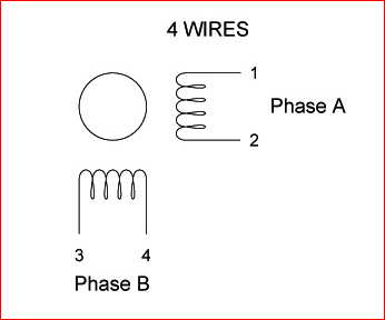
Bipolar Stepper
A bipolar stepper motor has one winding per stator phase. A two-phase bipolar stepper motor will have 4 leads. In a bipolar stepper, you don’t have a common lead like in a unipolar stepper motor. Hence, there is no natural reversal of the current direction through the winding.
A bipolar stepper motor has an easy wiring arrangement but its operation is a little complex. In order to drive a bipolar stepper, you need a driver IC with an internal H-bridge circuit. This is because, in order to reverse the polarity of stator poles, the current needs to be reversed. This can only be done through an H-bridge.
There are two other reasons to use an H-Bridge IC
- The current drawn by a stepper motor is quite high. The microcontroller pin can only provide up to 15 mA at maximum. The stepper needs a current which is around ten times this value. An external driver IC is capable of handling such high currents.
- Another reason why H-Bridge is used is that the stator coils are nothing but inductors. When coil current changes direction a spike is generated. evive’s digital pins cannot tolerate such high spikes without damaging themselves. Hence to protect its digital pins, H-bridge is necessary.
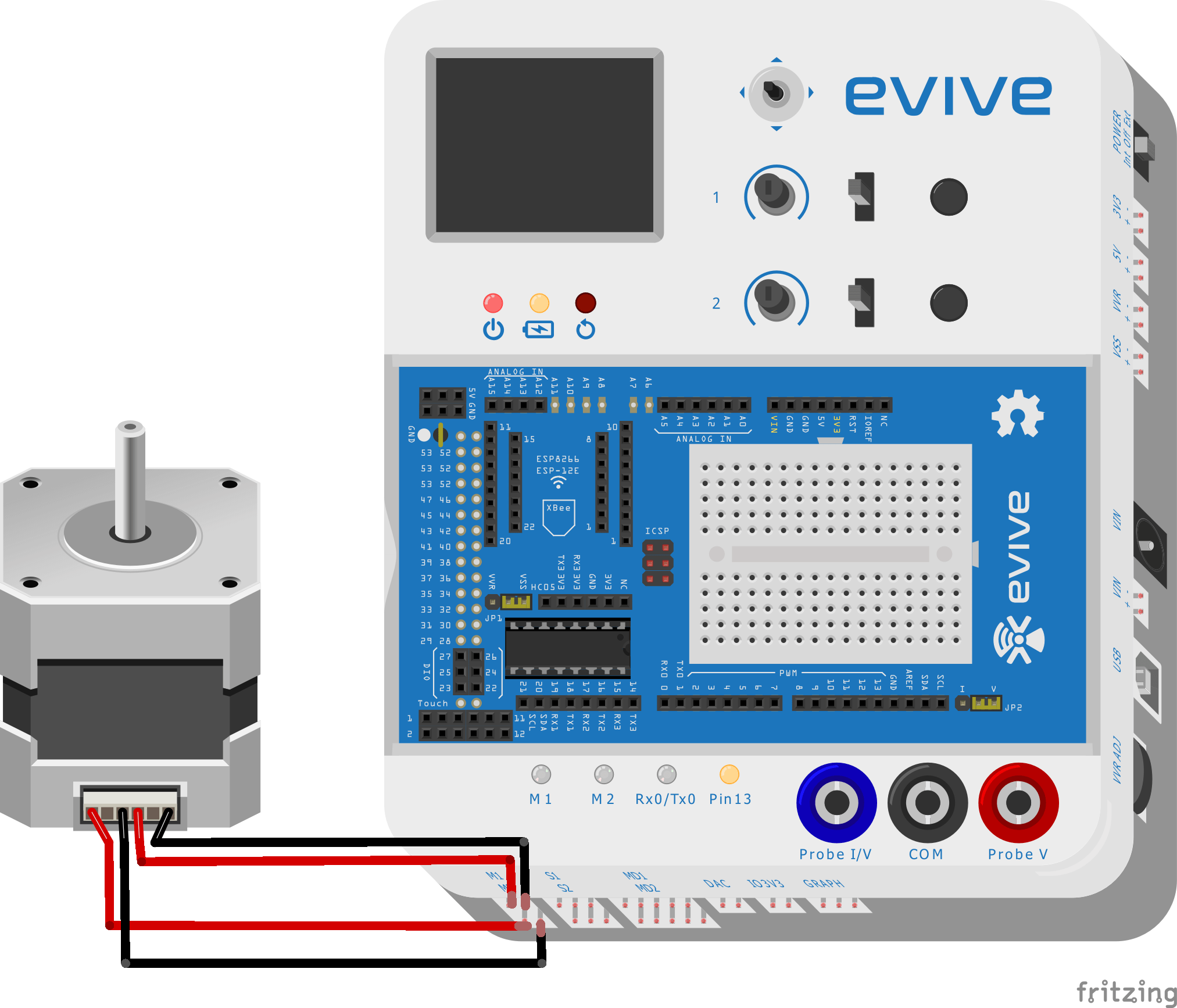
evive already has 2 H-bridges available for running a stepper motor. SN754410NE motor driver IC is used to run a bipolar stepper motor.
Stepping Sequence of Stepper Motors
Wave Drive Sequence
This is one type of stepping sequence. In this method, one phase is HIGH at a time. That is, when phase A is excited, all other phases are OFF. Similarly before exciting the next phase, the first is turned OFF. The winding is excited on by one for a finite duration like a wave, hence the name. Here is the stepping sequence diagram.
Full Step Sequence
The full step sequence or the 2 phase ON sequence, is when two adjacent phase windings are excited at a time so that the rotor is positioned at a point resultant to both the fields. Here is the stepping sequence diagram.
Half Step Sequence
This sequence is the mix of both the wave drive and full step stepping sequence. The first one of each of the above methods is used to form the first two of this message. By using this sequence, as you can see, the stepping angle is reduced by half.
Conclusion
In conclusion, stepper motors are brushless DC electric motors that divide a full rotation into a number of equal steps. They are powered by an external driver circuit or a microcontroller and come in two varieties: bipolar and unipolar. The stepping sequence used to drive the motor can vary, with wave drive, full step, and half step sequences being the most common. With an understanding of how stepper motors work and their various stepping sequences, you can effectively and efficiently use them for a variety of applications.


