Table of Contents

read analog pin ()

Description

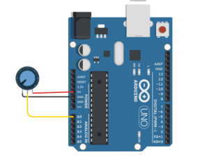
Read analog pin () is a reporter block found in evive blocks, Arduino Uno blocks, Arduino Mega blocks, and Arduino Nano block. The block returns the value of analog pins available in the connected hardware. Analog reading is of 10 bit resolution, hence the range of value is 0 to 1023. This range is mapped to the voltage of the pin (normally 0 to 5V). If the value received is 512, the voltage value will be around 2.5V.

Available Pins

  1. evive: 10 analog pins available for the user, A0 to A5 & A12 to A15
evive Notes Icon
Note: This block is available in both Upload mode and Stage mode.

Example

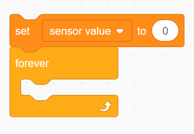
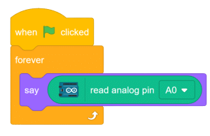
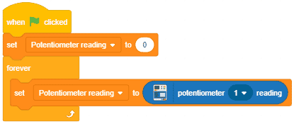
  1. Displaying the analog value of potentiometer 1 in stage mode.
    potentiometer example
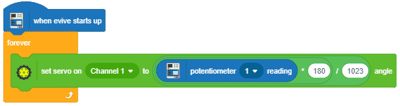
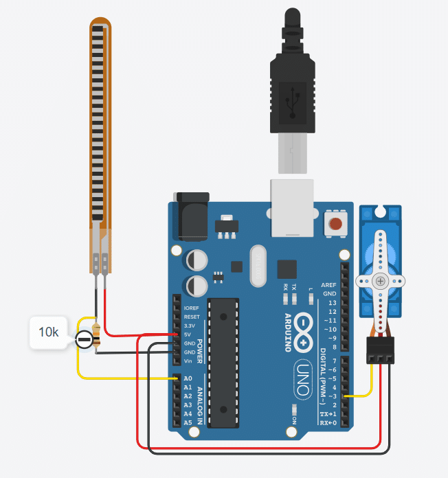
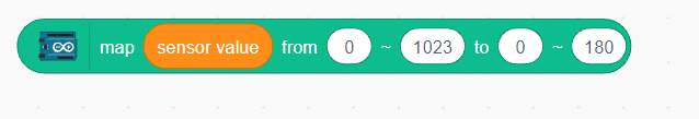
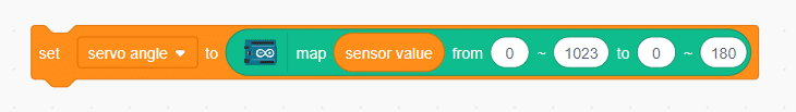
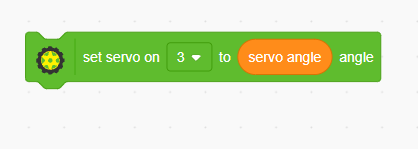
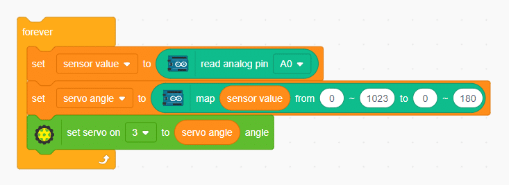
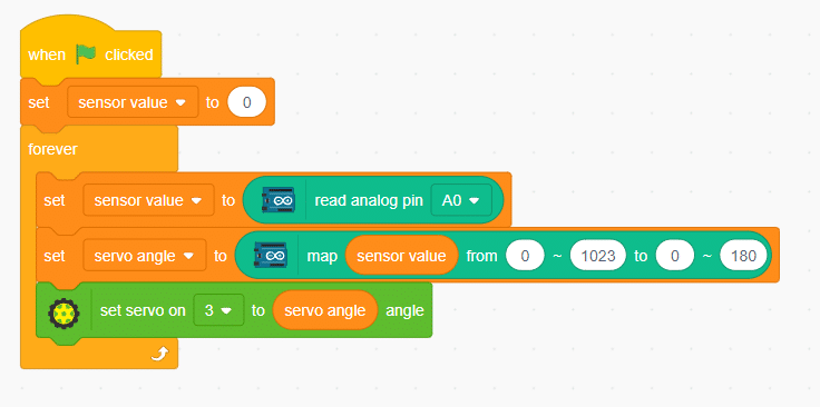
  2. Controlling servo motor connected to channel 1 of evive using the potentiometer 1.
    potentiometer example 2

Example

Explore the innovative flex sensor, utilizing carbon on a plastic strip to function as a variable resistor, with its resistance changing upon flexing the component
INTRODUCTION

The flex sensor is an ingenious device employing carbon on a plastic strip to serve as a variable resistor. As the sensor bends in one direction, its resistance varies accordingly. The more it bends, the higher the resistance becomes. This unique property makes it an ideal choice for applications where detecting bending or flexing is necessary.

Circuit Diagram


Code

  1. Create a variable called “sensor value” and set it to 0
  2. Add a “forever” block from the control palette. 
  3. Inside the “forever” block, set “sensor value” to read analog sensor at A0.
  4. Since the Arduino’s ADC channel is 8-bit, the generated value will range from 0 to 1023. To convert this range to 0-180 for controlling the servo motor, use the “map” block from the Arduino palette.
  5. Set the mapped value as the angle for the servo motor.
  6. connect servo at pin 3 and fed variable servo angle as for the servo motor.
  7. Add these three blocks inside the “forever” block to continuously read the flex sensor’s value and control the servo motor’s angle accordingly.
  8. Finally, add a “when flag clicked” event to complete the script and initiate the servo control with the flex sensor.

OUTPUT


Read More
Learn about the fundamental working principle of a potentiometer and its versatile applications as a variable resistor or voltage divider

Potentiometer and It’s working

A potentiometer is a crucial three-terminal resistor featuring a sliding or rotating contact that forms an adjustable voltage divider. When using only two terminals (one end and the wiper), it functions as a variable resistor or rheostat. The potentiometer’s three pins consist of two connected to the resistive element (blue and green) and one connected to the adjustable wiper (black). The potentiometer can serve as a rheostat to vary resistance or as a voltage divider. The position of the wiper determines the amount of resistance imposed on the circuit, as demonstrated in the figure below.

Circuit Diagram

Code

  1. From the event palette add when flag clicked event.
  2.  Add forever loop 
  3.  From looks palette add say block.
  4. Now add read analog pin A0 in this say block.

Script

Output

Read More
All articles loaded
No more articles to load