Introduction
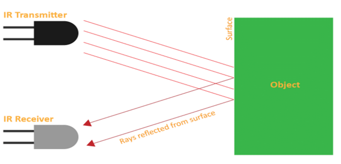
A Passive Infrared (PIR) motion sensor is a device commonly used in security systems, lighting control, and other applications to detect the presence of a moving object or person by measuring changes in infrared radiation. It’s called “passive” because it doesn’t emit any energy itself; it only detects the infrared radiation emitted by objects in its field of view.
- Detection Principle: PIR sensors work based on the fact that all objects with a temperature above absolute zero (-273.15°C or -459.67°F) emit infrared radiation. PIR sensors are designed to detect changes in the amount of infrared radiation in their surroundings.
- Sensor Construction: A PIR sensor typically consists of two pyroelectric sensors, which are sensitive to changes in temperature, and a special Fresnel lens that focuses the infrared radiation onto these sensors.

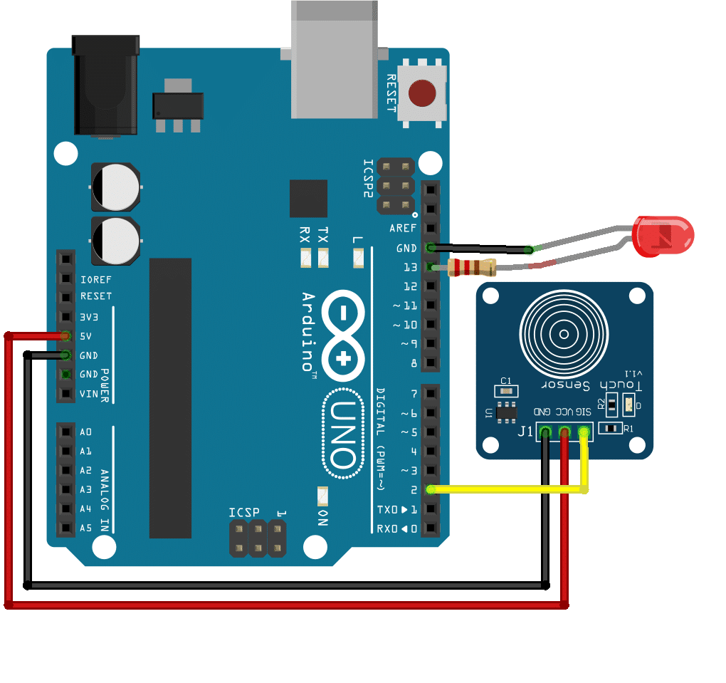
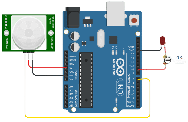
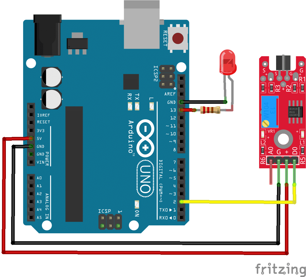
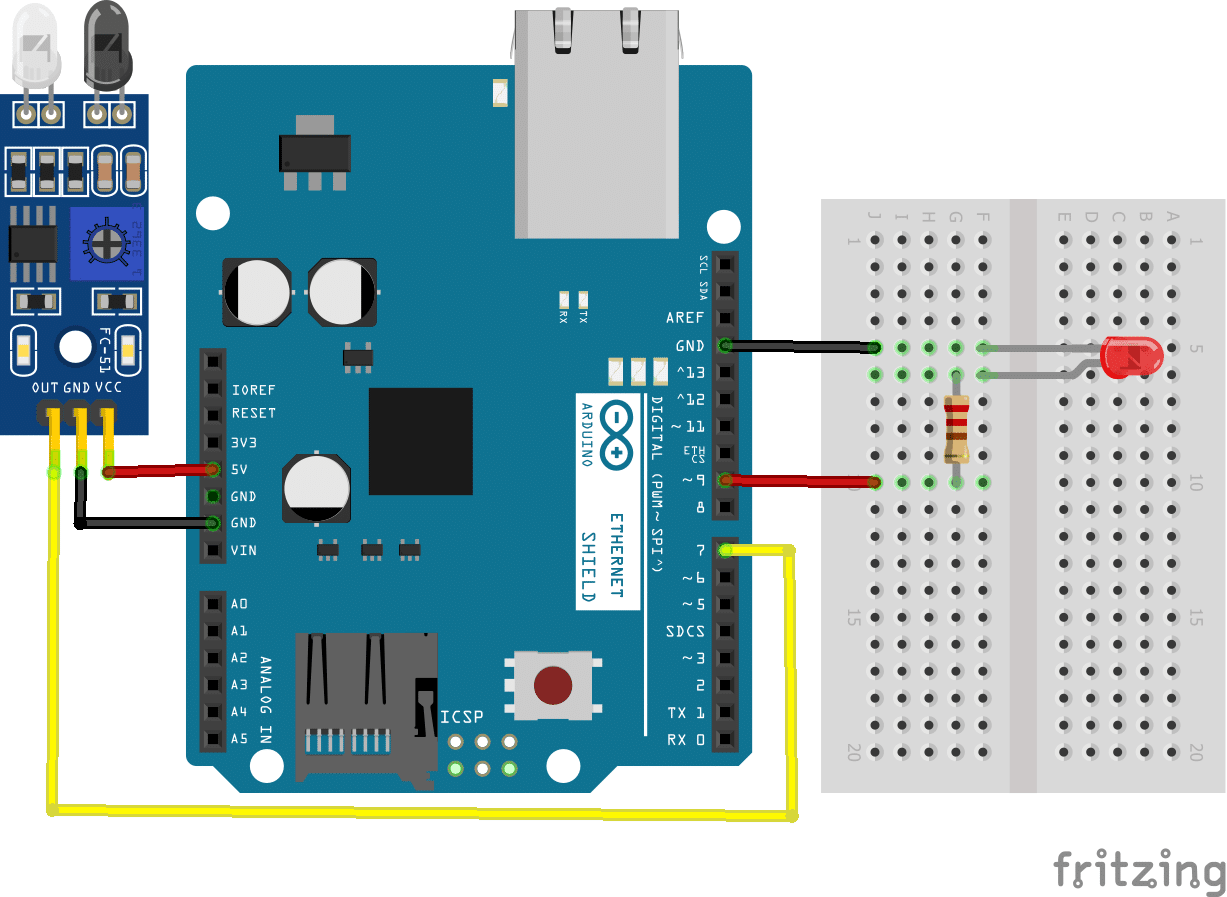
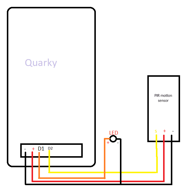
Circuit Diagram:
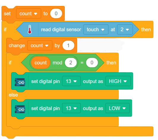
Code:
Follow these steps to implement the code using Pictoblox for Quarky to control the LED based on the PIR sensor’s readings:
- Open Pictoblox and create a new file in block coding.
- Go to boards and select Quarky.
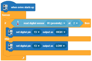
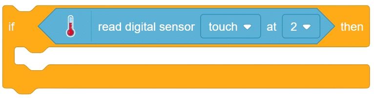
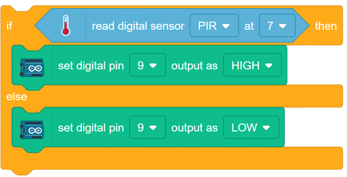
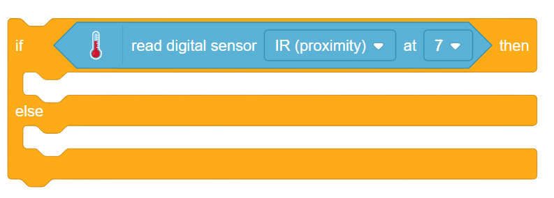
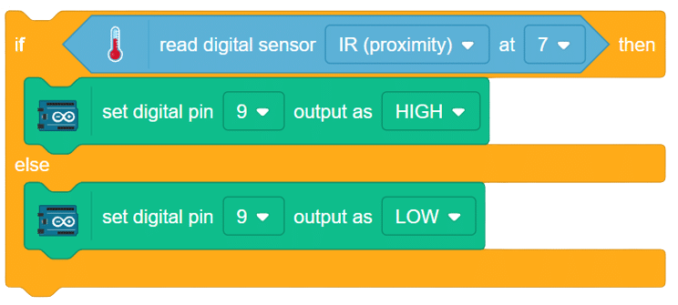
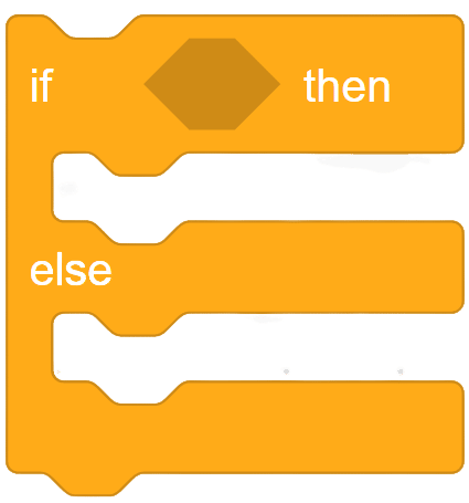
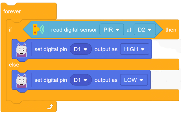
- Add an if-then-else block from the controls palette
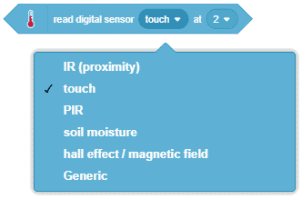
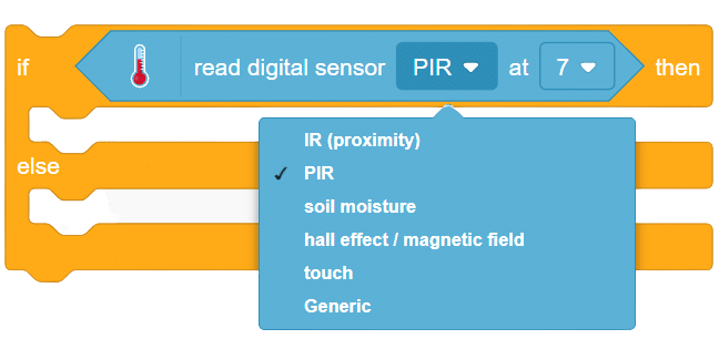
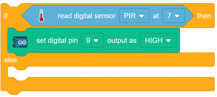
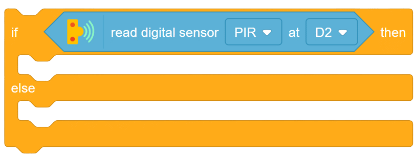
- From sensor palette of Quarky, add “read digital senor () at pin ()” block in if-then-else block.
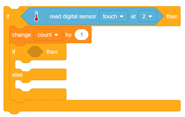
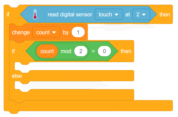
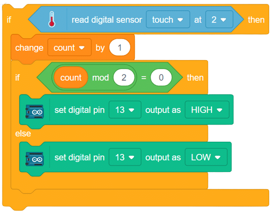
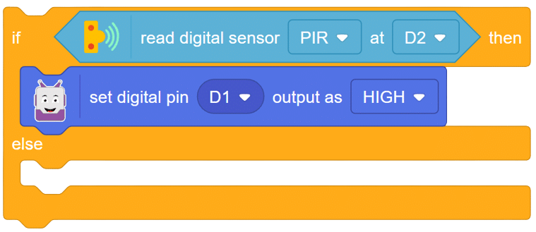
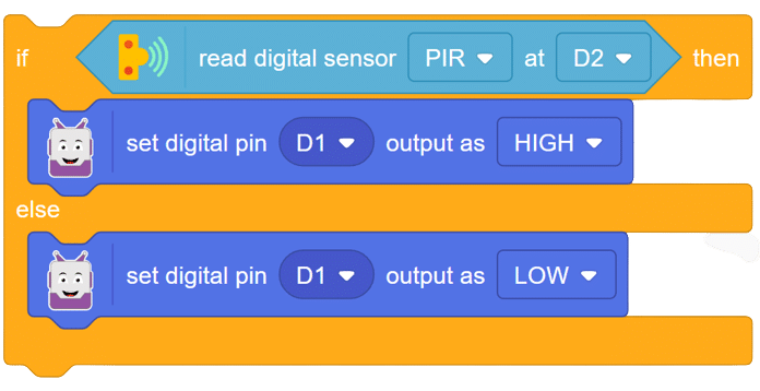
- Now if the D2 is high, the LED must turn ON by set D1 to High.
- Else the LED must remain OFF.
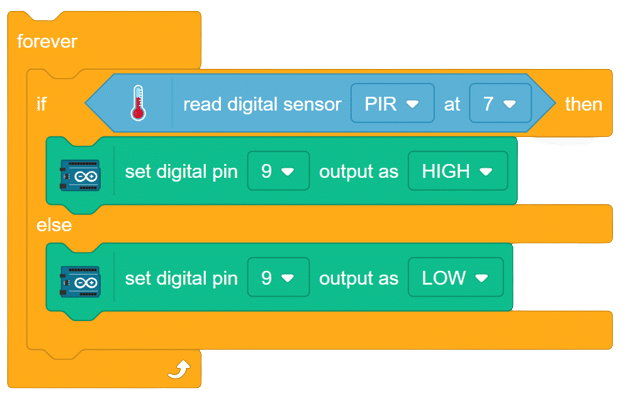
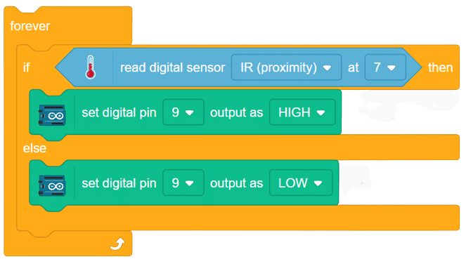
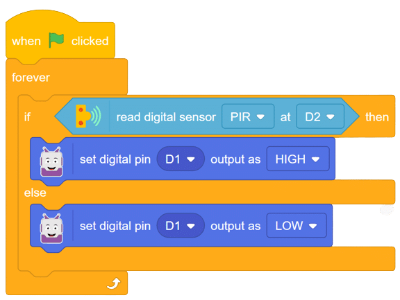
- Put the above set of code into the Forever block
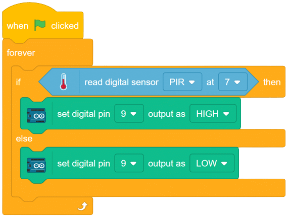
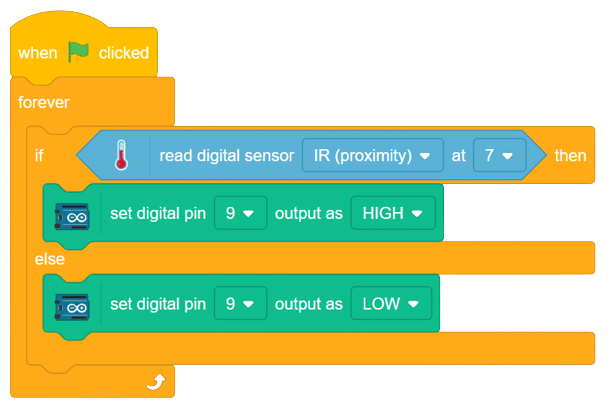
- Finally, add “when flag clicked” block at the start of the code. With this simple script your project is complete now.
OUTPUT
In this comprehensive introduction, you have learned about Quarky, the versatile microcontroller, and its potential in robotics and AI projects. Explore its various features, sensors, and plug-and-play functionality. Follow our step-by-step guide to set up the circuit with the PIR sensor and LED, and program Quarky using Pictoblox’s block coding. Witness the successful implementation through the final script and output, experiencing the magic of Quarky in action!