
Introduction
If you’re trying to grow some plants indoors, you’ll find that some rooms of your house are low in natural light. Sunlight is the perfect balance of wavelengths necessary for plant growth and blooming, but plants at different growth stages have special requirements of light.
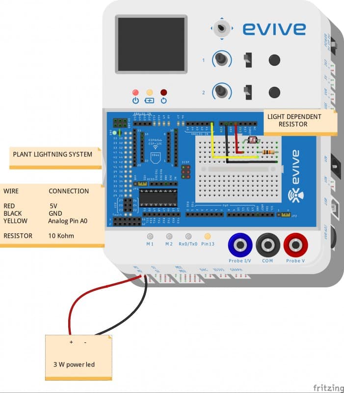
To provide the proper amount of lighting to plants and to carry out projects like indoor gardening a plant lighting system is required, which you will make in this project. LDR sensors will be used to keep track of the amount and the power LEDs are turned ON and the brightness is tuned accordingly.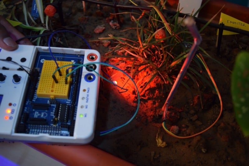
Which color light is best for plant growth?
Plants respond favorably to specific wavelengths of the light spectrum. In contrast, LED’s have the ability to produce wavelength specific light. This is the biggest advantage of LED in the indoor growing market. Each led emits a specific wavelength. Greenlight is the least effective for plants growth because of their green pigment Chlorophyll present on them. Different color light helps plants achieve different goals as well. Blue light, for example, helps encourage vegetative leaf growth. Red light, when combined with blue, allows plants to flower.
Light Dependent Resistor
LDR (wikipedia) are light sensitive devices most often used to indicate the presence or absence of light or to measure the light intensity. An LDR can be applied in light-sensitive detector circuits and light-activated and dark-activated switching circuits.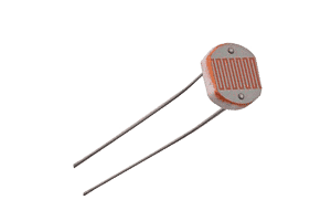
How does LDR sensor work?
The resistance of a photoresistor decreases with increasing incident light intensity. In other words, it exhibits photoconductivity. A photoresistor is made of a high resistance semiconductor. In the dark, a photoresistor can have a resistance as high as several megohms (MΩ), while in the light, a photoresistor can have a resistance as low as a few hundred ohms.
Setting up the circuit for LDR sensor
The circuit of LDR sensor is explained below
- One end of LDR is connected through jumper wire(red wire ) to the 5V power supply in the evive board.
- Another end of LDR is soldered with 10K resistor. Through the common junction of LDR and 10K resistor, a jumper wire is taken and hooked into the analog input(here we have used A1 pin number in the evive board) of the evive board.
- The free end of the resistor is grounded with the help of jumper wire(to make it more attractive the circuit can be placed inside the straw).

3W LED
The High Power LED is comparable in brightness to the standard incandescent and halogen light bulbs. This makes the High Power LED perfect for automotive, industrial, home and hobby applications. Not only are they bright, but they also consume a fraction of power of an incandescent bulb making them extremely energy efficient
The High Power LED incorporates an aluminum heat sink to dissipate heat. Simply connect the large + and – pads on the PCB to a current limited power source to enable the LED.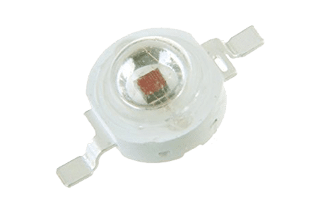
Setting up the circuit for 3W LED
Before making circuit connections, we need to know the following things regarding Blue and red power LED:
-
For high power red LED the working voltage: 2.0v-2.5v Typical: 2.1vCurrent: 650-700mA.
- For high power blue LED the working voltage: 3.0v-3.5v Typical: 3.3 vCurrent: 650-700mA.
The connections of the power LED are explained below :
- Connect the female end of the jumper wire to the motor pin.
- Solder the 3 W power d. Make sure you remember the positive and negative end of the power LED. For safety, you can use a red wire for positive an black wire for negative.
- Now, connect the positive end of the motor pin to the positive end of the LED.
- We have set the PWM pin to 35 (by trial) and 2.0 V. At this condition red LED will to work fine.
- Make sure you don’t apply the voltage more than 2V.
Logic
The logical flow of the program is very simple:
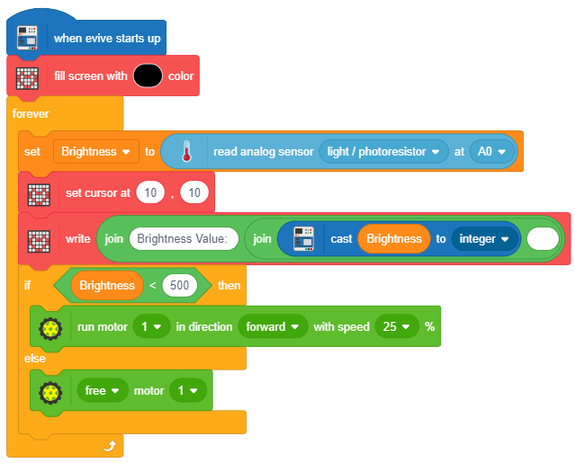
- Get the brightness value from the sensor.
- Display brightness value on the screen.
- If the brightness value is less than 500, that means brightness is low, then power ON the LED.
- If the brightness is greater than 500, that means its day time, then power OFF the LED.
PictoBlox Program
Follow the steps:
- Open PictoBlox, select the board as evive.
- Connect your COM port to evive.
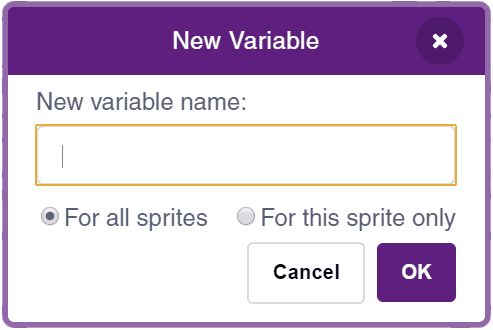
- Create a variable to store the brightness value:
- Create the script using when evive starts up block following the logic stated in the previous step.
- Upload the Code onto evive:

Output
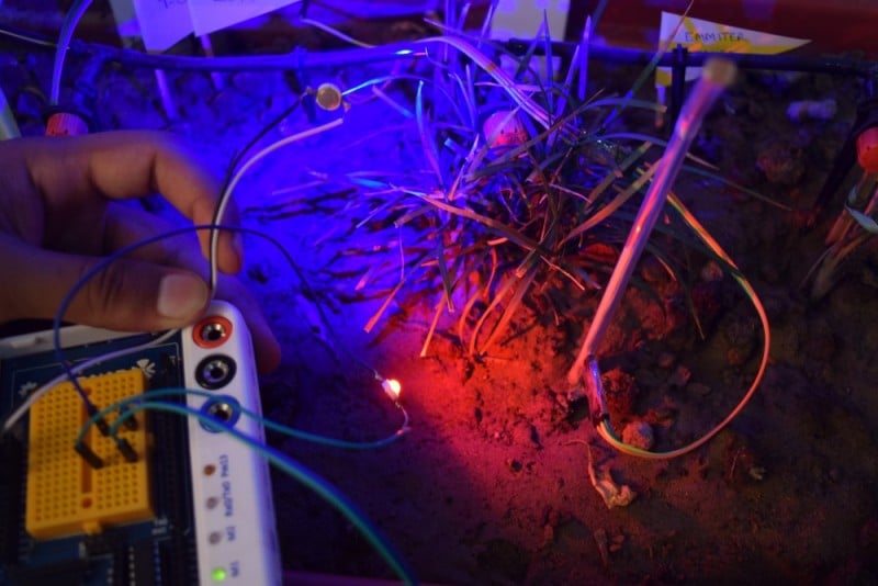
The power LED provide lightning to the plants as shown in the figure.


 2-53 screenshot")


