Introduction
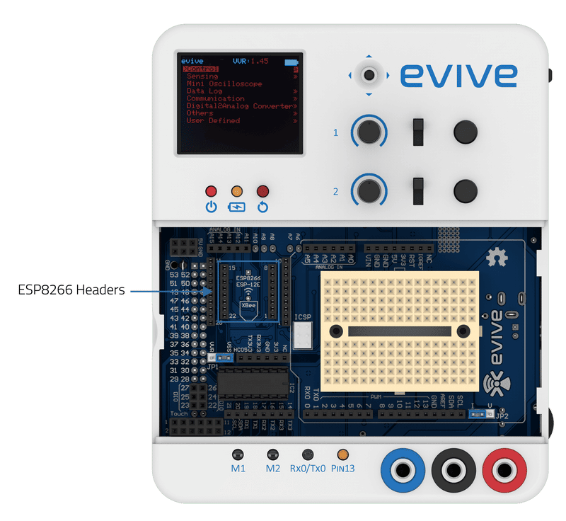
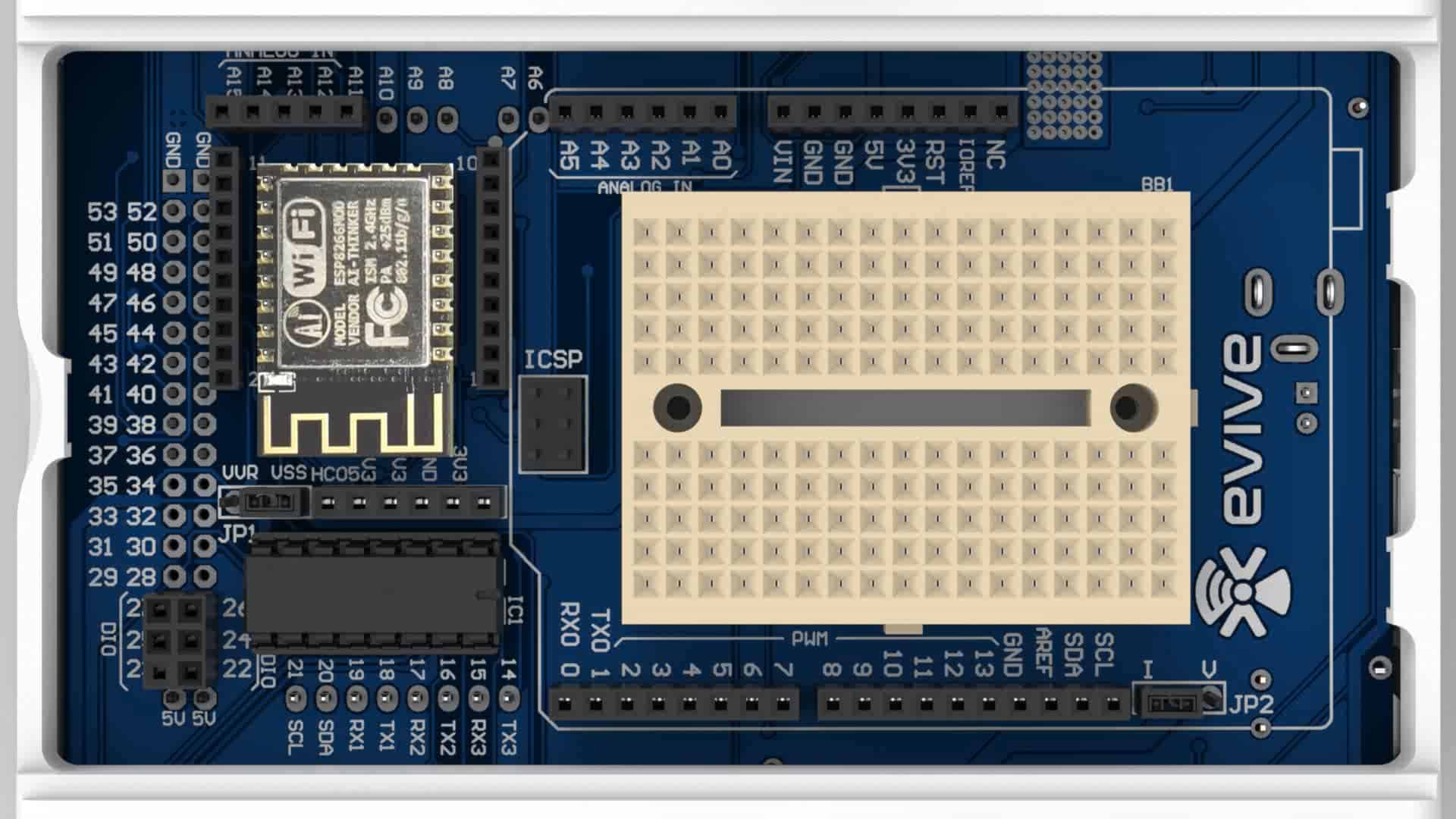
evive has dedicated WiFi headers, which just require you to connect the ESP8266 WiFi module. Communication between evive and the WiFi module occur via serial port 3.
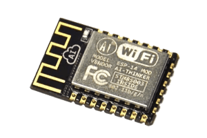
ESP8266 WiFi Module
ESP8266 WiFi Module is a self-contained SOC with integrated TCP/IP protocol stack that can give any microcontroller access to your WiFi network. The ESP8266 is capable of either hosting an application or offloading all Wi-Fi networking functions from another application processor. Each ESP8266 module comes pre-programmed with an AT command set firmware, meaning, you can simply hook this up to your evive and get about as much WiFi-ability as a WiFi Shield offers.
Features:
- 11 b/g/n
- Wi-Fi Direct (P2P), soft-AP
- Integrated TCP/IP protocol stack
- Integrated TR switch, balun, LNA, power amplifier, and matching network
- Integrated PLLs, regulators, DCXO, and power management units
- +19.5dBm output power in 802.11b mode
- Power down leakage current of <10uA
- An integrated low power 32-bit CPU could be used as an application processor
- SDIO 1.1 / 2.0, SPI, UART
- STBC, 1×1 MIMO, 2×1 MIMO
- A-MPDU & A-MSDU aggregation & 0.4ms guard interval
- Wake up and transmit packets in < 2ms
- Standby power consumption of < 1.0mW (DTIM3)
ESP8266 AT Command Set
| Function | AT Command | Responce |
|---|---|---|
| Working | AT | OK |
| Restart | AT+RST | OK [System Ready, Vendor:www.ai-thinker.com] |
| Firmware version | AT+GMR | AT+GMR 0018000902 OK |
| List Access Points | AT+CWLAP | AT+CWLAP +CWLAP:(4,"RochefortSurLac",38,"70:62:b8:6f:6d:58",1) +CWLAP:(4,"LiliPad2.4",-83,"f8:7b:8c:1e:7c:6d",1) OK |
| Join Access Point | AT+CWJAP? AT+CWJAP="SSID","Password" | Query AT+CWJAP? +CWJAP:"RochefortSurLac" OK |
| Quit Access Point | AT+CWQAP=? AT+CWQAP | Query OK |
| Get IP Address | AT+CIFSR | AT+CIFSR 192.168.0.105 OK |
| Set Parameters of Access Point | AT+ CWSAP? AT+ CWSAP= | Query ssid, pwd chl = channel, ecn = encryption |
| WiFi Mode | AT+CWMODE? AT+CWMODE=1 AT+CWMODE=2 AT+CWMODE=3 | Query STA AP BOTH |
| Set up TCP or UDP connection | AT+CIPSTART=? (CIPMUX=0) AT+CIPSTART = (CIPMUX=1) AT+CIPSTART= (CIPMUX=0) AT+CIPSTART = (CIPMUX=1) AT+CIPSTART= | Query id = 0-4, type = TCP/UDP, addr = IP address, port= port |
| TCP/UDP Connections | AT+ CIPMUX? AT+ CIPMUX=0 AT+ CIPMUX=1 | Query Single Multiple |
| Check join devices' IP | AT+CWLIF | |
| TCP/IP Connection Status | AT+CIPSTATUS | AT+CIPSTATUS? no this fun |
| Send TCP/IP data | (CIPMUX=0) AT+CIPSEND= (CIPMUX=1) AT+CIPSEND= | |
| Close TCP / UDP connection | AT+CIPCLOSE= | |
| Set as server | AT+ CIPSERVER= | mode 0 to close server mode; mode 1 to open; port = port |
| Set the server timeout | AT+CIPSTO? AT+CIPSTO= | Query |
| Baud Rate* | AT+CIOBAUD? Supported: 9600, 19200, 38400, 74880, 115200, 230400, 460800, 921600 | Query AT+CIOBAUD? +CIOBAUD:9600 OK |
| Check IP address | AT+CIFSR | AT+CIFSR 192.168.0.106 OK |
| Firmware Upgrade (from Cloud) | AT+CIUPDATE | +CIPUPDATE:1 found server +CIPUPDATE:2 connect server +CIPUPDATE:3 got edition +CIPUPDATE:4 start update |
| Received data | +IPD | (CIPMUX=0): + IPD, (CIPMUX=1): + IPD, |
| Watchdog Enable* | AT+CSYSWDTENABLE | Watchdog, auto restart when program errors occur: enable |
| Watchdog Disable* | AT+CSYSWDTDISABLE | Watchdog, auto restart when program errors occur: disable |
Example
/*
	This example is used to communicate with peripherals connected to Serial3 Port.
	Messages/Data read from Seripa Port 3 will be sent to Serial Port 0 (connected to USB) and vice-versa.

	Just simply change BAUD rate to your desired and open Serial Monitor in Arduino IDE

	Note: Make sure you have selected Both NL and CR at bottom of Serial monitor with proper baud

	Made by Nihar Shah, Agilo Research
	On 12 October 2017.
*/

void setup() {
  Serial.begin(250000);							// Start Serial 0 (USB) at BAUD rate 250000
  Serial3.begin(115200);						// Start Serial 3 at BAUD here as per the module
  delay(50);
  Serial3.print("AT\r\n");    			// AT to check whether device is connected or not? Typically Replies with OK
}

void loop() {

  while (Serial.available())				//Checks wether any data is recieved on Serial (USB) (Serial Port 0)
  {
    Serial3.write(Serial.read());		//Reads the data from Serial Port 0 and send/write it to Serial Port 3
  }

  while (Serial3.available())				//Checks wether any data is recieved on Serial Port 3
  {
    Serial.write(Serial3.read());		//Reads the data from Serial Port 3 and send/write it to Serial Port 0
  }
  delay(100);
}
Conclusion
In this lesson, we discussed how to use the ESP8266 WiFi module with evive. We learned the features of the ESP8266 WiFi module, as well as how to connect it to evive and send and receive data through the serial ports. We also looked at an example of how to send and receive data between evive and the ESP8266 WiFi module. With this knowledge, you should now be able to use the ESP8266 WiFi module with evive to create projects that involve wireless communication.


