
Introduction
It may not know who you are. But it will look for you and it will find you. And nothing that comes in its way will be spared by it. It is none other than the determined and precise Line Following Robot!
Enough of the filmy stuff. Who’s all excited to make one with us? Bet you are!
So, why wait any longer? Ready. Set. DIY!
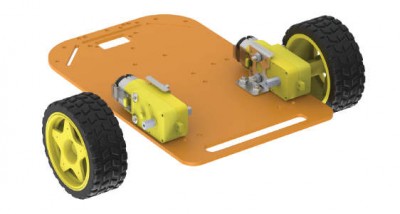
Assembly
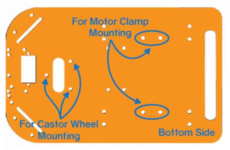
- The following image shows the annotated base, which is the bottom layer. The top layer has the evive’s logo.
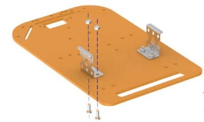
- Fix the motor mounting brackets to the chassis using M3 bolts of 8mm length and M3 nuts.

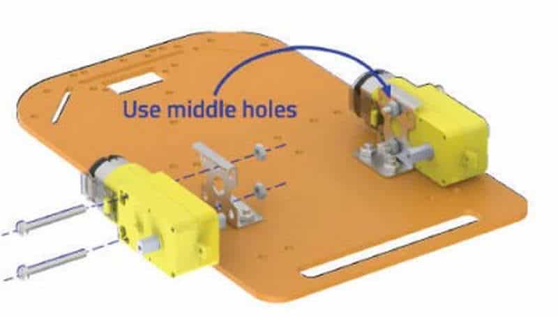
- Attach the two motors, one to each bracket, side by side and fasten using M3 bolts of 25mm length and M3 nuts.
- Now, fit the wheels into the protruding motor shafts.
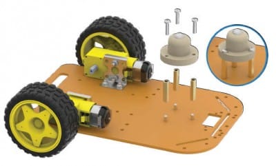
- We’ll attach the Castor wheel now. First, we will mount the M3 standoffs (20 mm) on which we will attach the castor wheel. Fasten the standoffs to the chassis using M3 bolts of 8mm length.
- Place the Castor on top of the standoffs in the configuration shown and fasten using M3 bolts of 12 mm length.

- Flip the assembly and place evive on the top of the chassis.
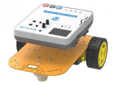
- Using the holes on the back of evive fasten it to the chassis using M3 bolts of 12mm length.
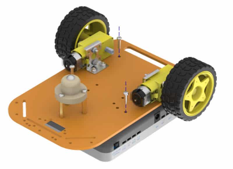
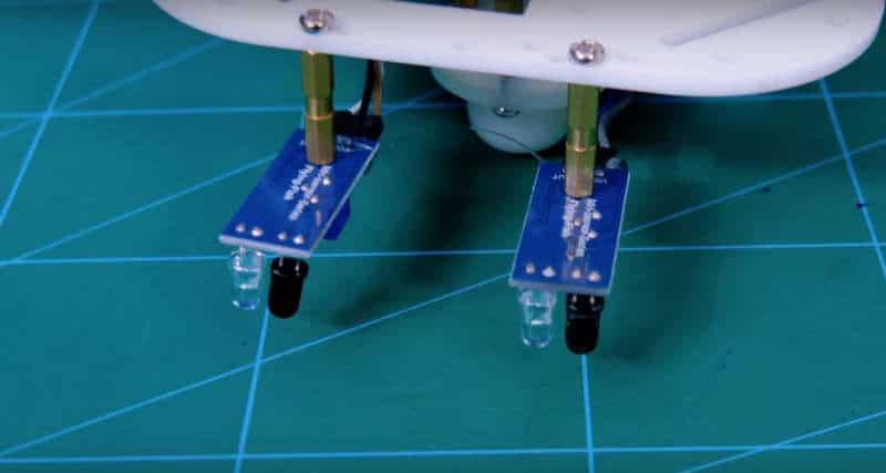
- We will now attach 2 IR sensors onto the front of the robot.
- For that, attach 2 standoffs of 15mm length using M3 bolts of 8mm length.
- Place the IR Sensors on the standoffs, using M3 bolts of 8 mm length.
- Make Sure: That the potentiometer over the sensor should be facing downwards.
- Finally, bend the LEDs on the IR Sensor downwards.
- Flip the assembly.
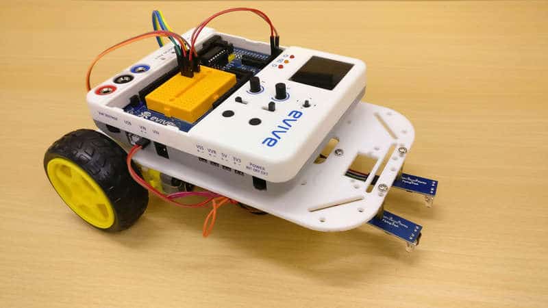
Your Line Following Robot is now ready.
Calibration of IR Sensor
For different materials calibration for IR Sensor is done differently. As for making the path which the line follower will follow, we will be using the black chart paper or the black tape.
Thus, we now need to calibrate our sensor according to them.
Now, to calibrate your sensor, place a piece of tape or chart paper below the robot at the distance which will be equal to the distance between the IR Sensor and the ground.
Here, as we have programmed it, we can directly see on the screen whether the sensor is calibrated or not. The two round rectangles on the screen indicated the IR Sensor corresponding to their sides.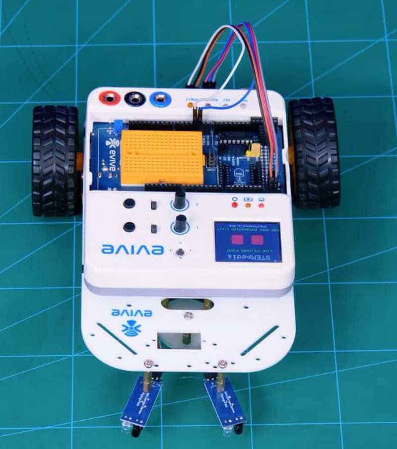
Let’s calibrate the left one:
If we place the chart paper below the IR Sensor, the left round rectangles should turn ‘GREEN’, if not gently turn the potentiometer (that tiny blue cube with a screw in it) with a screwdriver.
If that is done, take the chart paper off and now the round rectangles should turn RED, if not turn the potentiometer in the other direction.
This should be the screen when you calibrated the left one: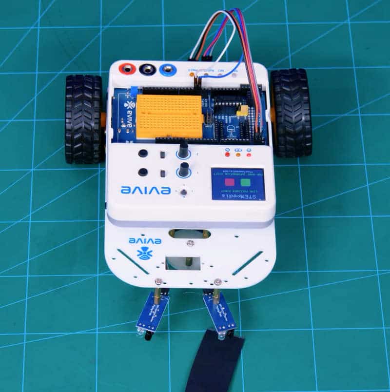
Thus, one of your sensors is calibrated.
Now, repeat the same process with the right sensor.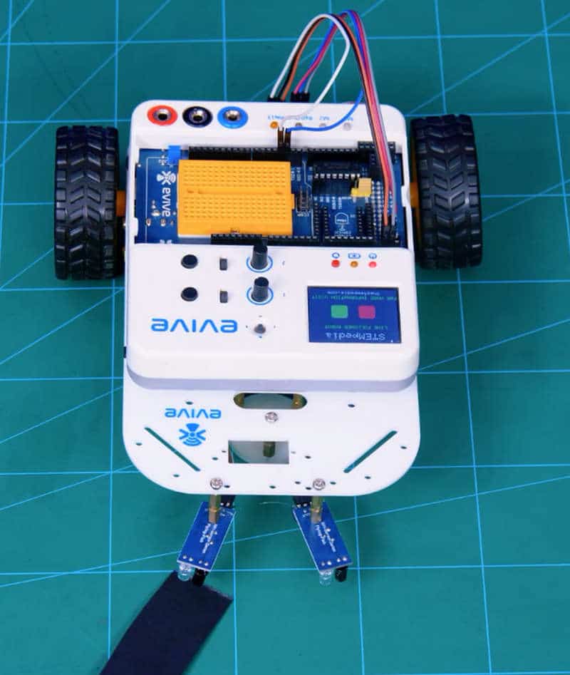
And you’re done; your sensor is calibrated.
Logic
How, or rather when the robot follows anything depends on the state of the two sensors.
- If both sensors are OFF / RED, the robot should move in the forward direction.
- If only the sensor on the right is ON / GREEN, the robot should turn right.
- Similarly, if only the sensor on the left is ON / GREEN, the robot should turn left.
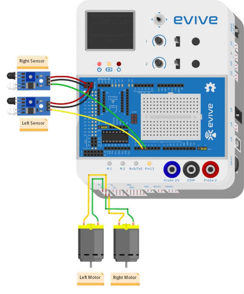
Circuitry of the Robot
We will connect the two DC Motors to M1 and M2.
And the IR Sensors are connected as:
- VCC – 5V of evive
- GND – GND of evive
- OUT – Digital Pin 3, 4
Code
The following code will help you to make the Line Following Robot:
Conclusion:
With this, your Line Following Robot is ready for action! Go ahead and watch it follow the tracks laid down by you effortlessly.


 2-53 screenshot")


