
Introduction
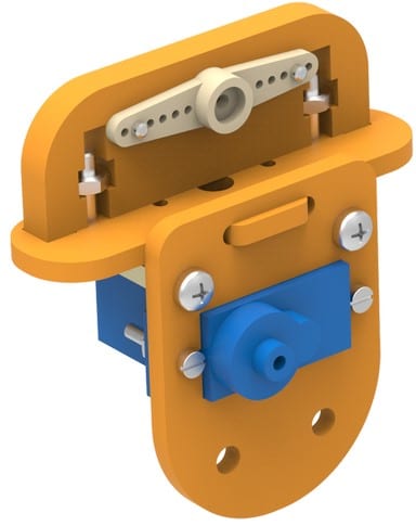
A gripper is a device which enables the holding of an object to be manipulated. The easier way to describe a gripper is to think of the human hand. Just like a hand, a gripper enables holding, tightening, handling and releasing of an object. The gripper you get with the Robotic Arm kit is actuated using Servo Motor.
Assembly
-
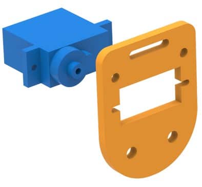
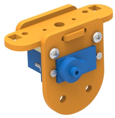
- Insert micro servo into the slot on the gripper plate as shown, then affix it there using M2 bolts of 8mm length and M2 nuts.
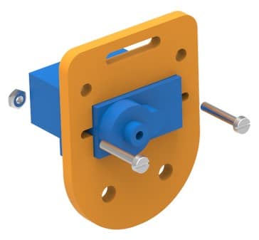
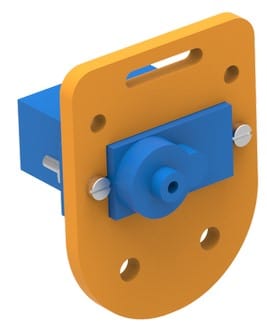
- Fasten 15mm standoffs to the plate using M3 bolts of 8mm length.
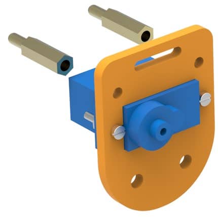
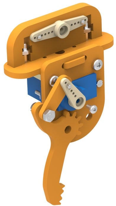
- Insert gripper part 1 into the thin slot provided on the gripper plate. Note that this part is not symmetric and the small square slots are nearer to one end than to the other. Do insert this in the exact configuration as shown in the figure.
Observe how the square holes are further away from the plate compared to the other end of gripper part 1. - Slide gripper part 2 (with a thin slit) onto the protrusion on gripper part 1.
- Notice that gripper part 2 has holes 3mm in diameter so that threaded part of standoffs may pass through it. Fasten these parts using M3 nuts.
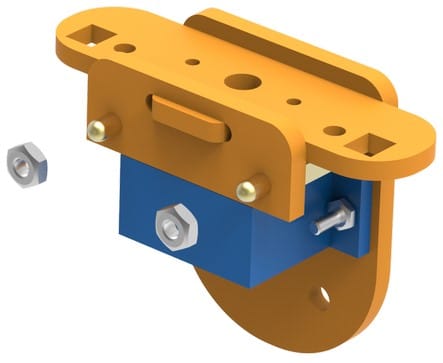
- Insert gripper part 3 into the rectangular holes of gripper part 1 as shown and place M3 nuts and fasten using M3 bolts of 12mm length.
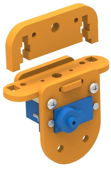
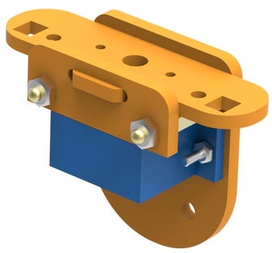
- Now attach a micro servo horn on gripper part 3 with its holes aligned with the holes on gripper part 3 and fasten with self-threading M2 bolts of 8mm length (from micro servo accessories).
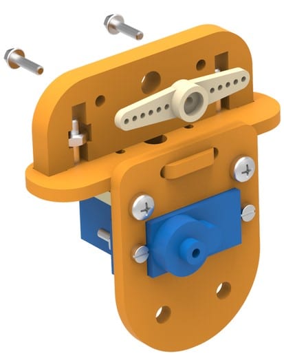
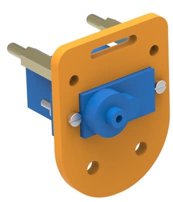
- Bring together gripper claw 1, gripper link and a one sided micro servo horn in the configuration shown. First, fasten gripper link to the one sided micro servo horn using self-threading M2 bolt from micro servo accessories. Keep in mind, protruded end of servo horn should be facing the servo.
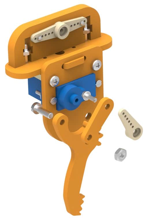
- Next, insert the M3 bolt of 12mm length to gripper claw 1 as shown. Hold the “gripper link and servo horn” assembly intact. Then insert gripper link 1 onto this bolt and fasten an M3 lock nut on the same. Ensure than the links are movable about the bolt but they shouldn’t be too loose.
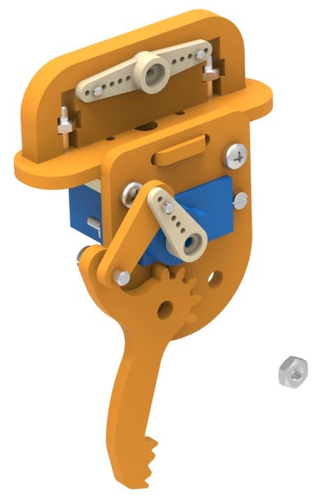
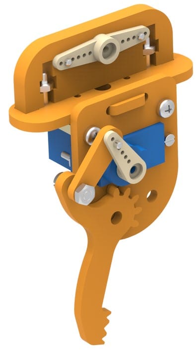
- Insert micro servo into the slot on the gripper plate as shown, then affix it there using M2 bolts of 8mm length and M2 nuts.
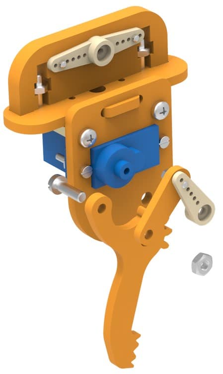
- Now lock the one sided micro servo horn and the free servo head using the self-threading bolt from micro servo accessories. Ensure the micro servo is at 90 degrees before assembling
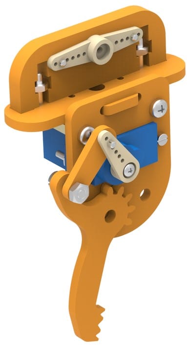 .
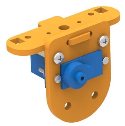
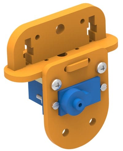
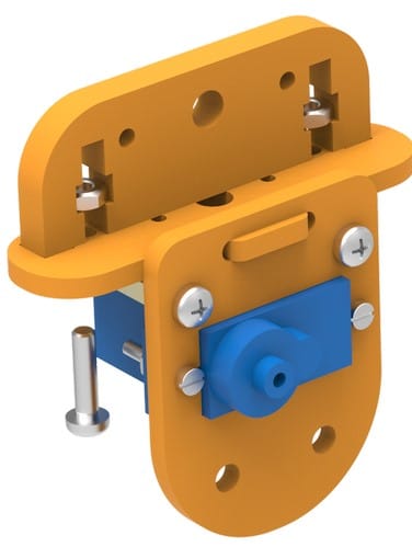
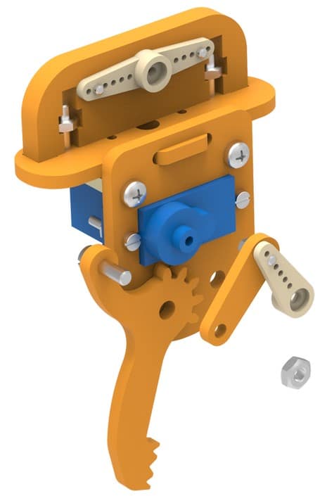
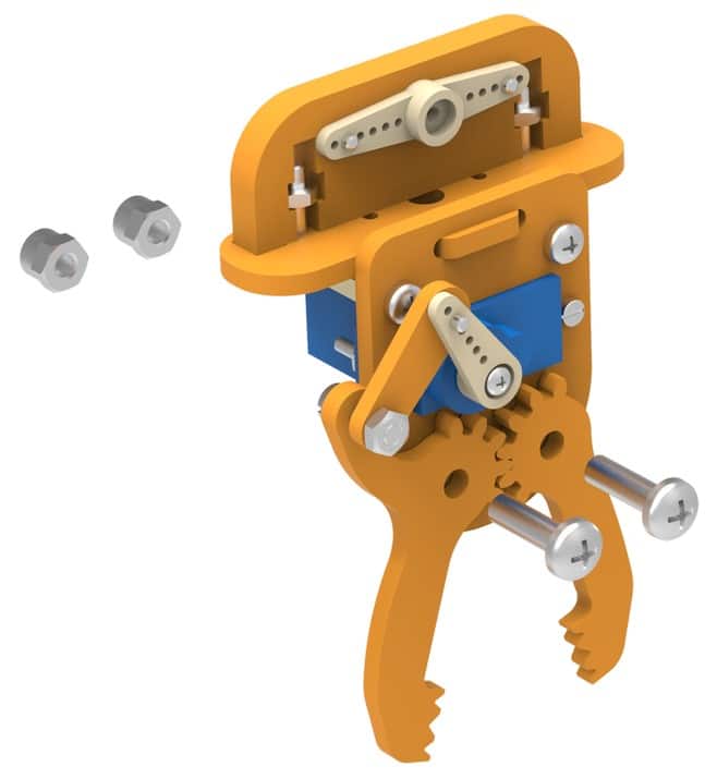
. - Now, note that there is a free hole on gripper plate and that gripper claw 1 is in front of the other hole. Intuitively, place gripper claw 2 on the other hole. Now M4 bolts of 16mm length in both these holes and fasten using M4 lock nuts. Keep in mind that claws aren’t too loose but are free to rotate about these bolts.
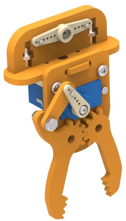
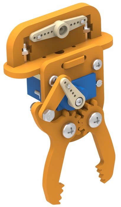
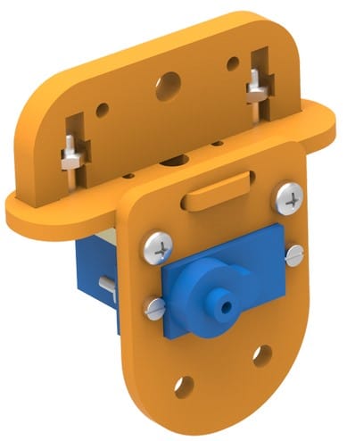
Your Gripper is Complete :), Now we have to program it.
Controlling Gripper Using evive
Circuit Diagram
In the following example, I will be showing you how to control servo through channel 1. Given below is the circuit diagram:
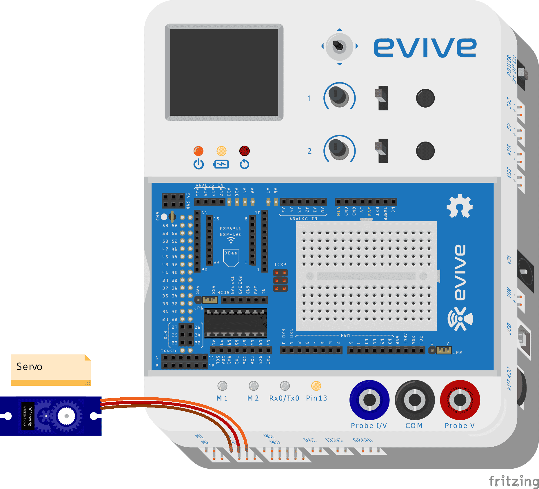
A Servo pin has three wires (Order to be connected in evive, left to right)
- Brown wire: GND
- Red wire: VCC
- Orange wire: Signal
evive Firmware
Upload the latest firmware into evive using Arduino IDE. If you don’t have firmware installed, download it from here. If you don’t have Arduino installed, go through this page to install Arduino.
Once you have uploaded the firmware into evive, go through the following steps:
- In the firmware, the first option is Control. Using the navigation key, click right and you will enter control submenu.
- In control submenu, you will find three options:
- Motors
- Servos
- Stepper Motor
Navigate to Servo.
- In side servo motor control you will see another three options:
- Servo 1 (To control servo motor through channel 1)
- Servo 2 (To control servo motor through channel 2)
- Servo 1 and 2 (To control both servo motor)
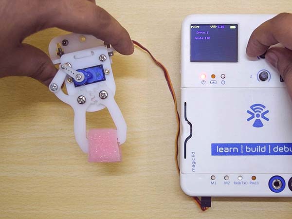
Select Servo 1 for this case
- Now you will see a panel, where on the left half you see angle set on servo channel 1. Using Potentiometer 1 you can control the servo angle ranging from 0 to 180 degrees.
Control using Arduino IDE
Use the following code to control The gripper:
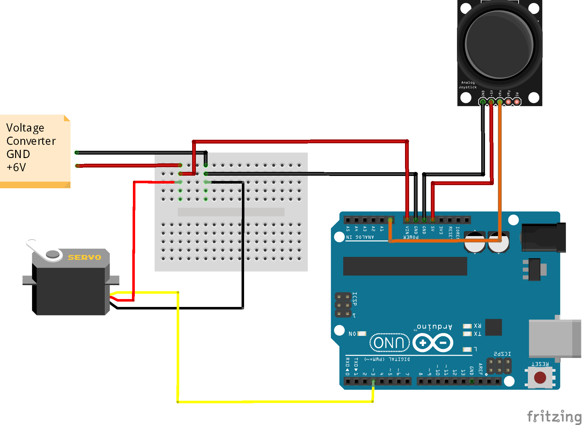
Controlling Gripper using Arduino Uno
Arduino uno has 6 PWM pins: 3, 5, 6, 9, 10, and 11 which provide 8-bit PWM output with the analogWrite() function.
We will controlling servo using Pin 3.
Circuit Diagram

Code


 1-18 screenshot")


