
Introduction
And we’re back with another DIY gaming project! As always, playing with something made with your own hands is always an out-of-the-world experience! First, it was a DIY Game Controller; now it’s time for a DIY Joystick using Accelerometer!
This time we’re going to make a DIY Joystick using an accelerometer using which you can control a robotic arm, an entire robot, and even play many games!
Ready to transform your gaming experience? Then begin right away!
Assembly
We have interfaced the accelerometer with our 2 previously made robots. Whose assembly you can find on the link given below.
And will also use as:
- A Game Controller
The catch here is that we will be using the accelerometer to control the movements of robots or the game sprite.
The Accelerometer cannot be just held in hands. Thus, we are using a 3D printed holder.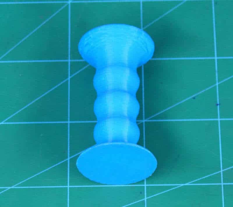
We have attached the Accelerometer on the top of the holder.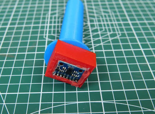
With this, we have completed our assembly part.
What is Accelerometer?
What is the Accelerometer:
An Accelerometer is a device used to measure the acceleration, which is nothing but the change in velocity with respect to time. To be precise, the accelerometer we use here measures the change in the gravitational acceleration.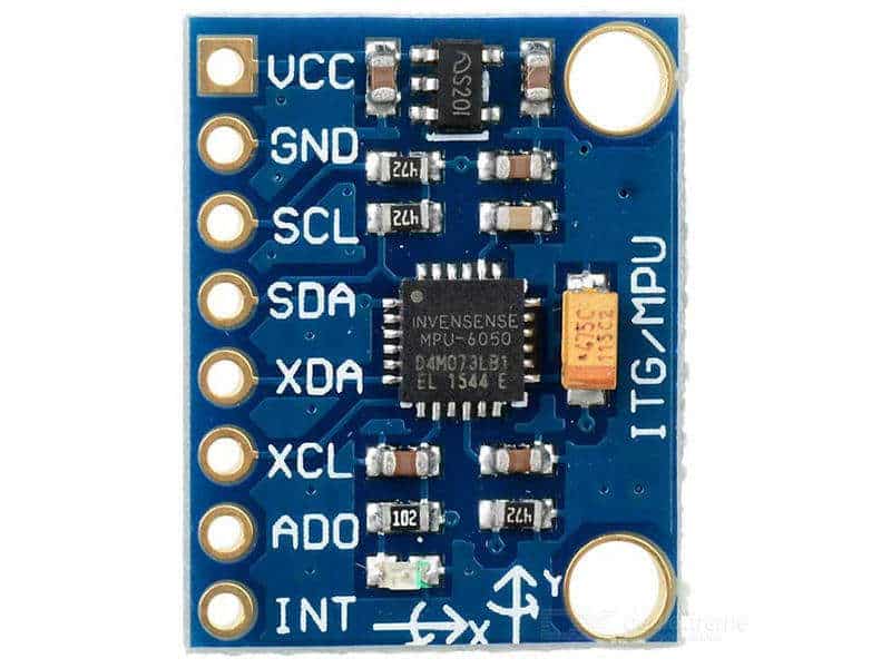
Working of Accelerometer:
There are many ways in which an accelerometer works. But, the major ones are the piezoelectric effect and the capacitive effect.
The piezoelectric effect is the most popular one. In this technique, there is a microscopic crystal which is stressed due to the presence of accelerative forces. The charge is then accumulated on the crystal which is then amplified or turned into output voltage or current.
The capacitive accelerometer senses the change in the capacitance between two microstructures which in turn changes to the output voltage.
These methods thus detect the change in all the three axes i.e. x, y or z on tilting the device.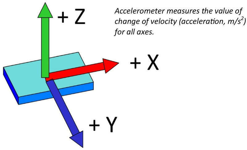
Logic
As we know, our sensor can respond in specific values to any tilt or movement in its x, y, or z-axes. We will be using this property and will assign specific actions for each change.
- In Mobile Robot:
- Tilt Forward – Robot moves Forward
- Tilt Backward – Robot moves in Reverse Direction
- Tilt Right – Robot turns Right
- Tilt Left – Robot turns Left
- No Tilt – Brake
- In Robotic Arm:
- Tilt Forward – Base Servo will turn Left
- Tilt Backward – Base Servo will turn Right
- Tilt Right – Link Servo will turn Right
- Tilt Left – Link Servo will turn Left
- No Tilt – Stop
- As Game Controller
- Tilt Forward – Jump / Space
- Tilt Backward – Shoot / Shift
- Tilt Right – Game Sprite will move Forward
- Tilt Left – Game Sprite will move Backward
- No Tilt – Stop
Circuit Diagram
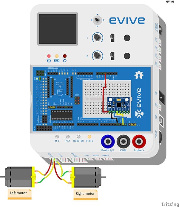
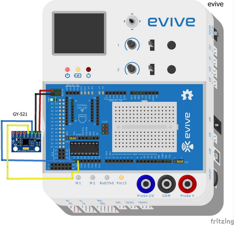
The following circuitry is for the Mobile Robot:
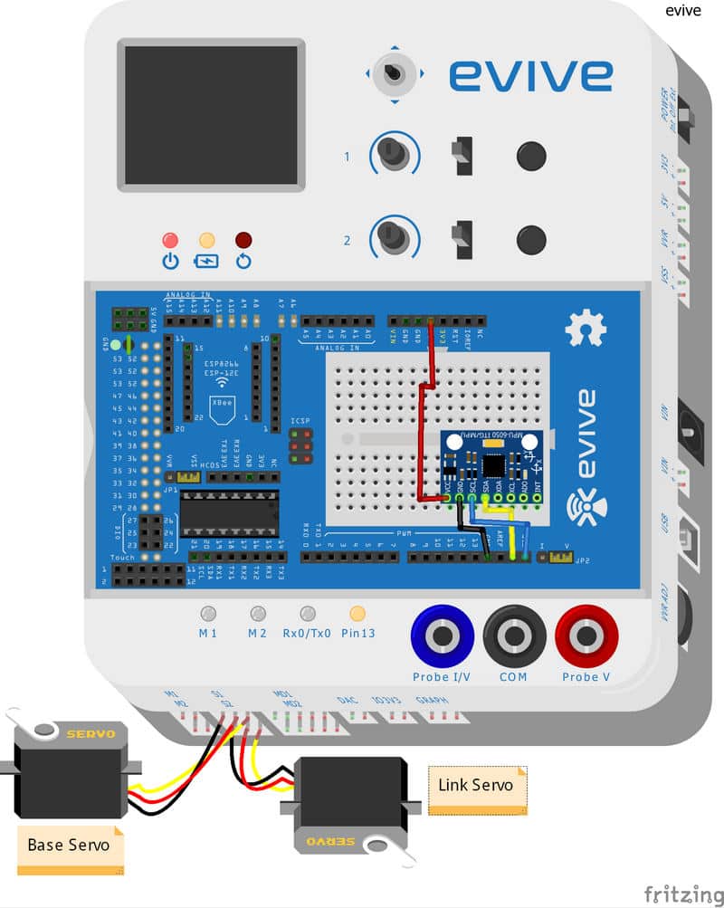
The circuitry for the Robotic Arm is as follows:
The connection for how the Accelerometer to be used as Game Controller is shown below:
Code
Mobile Robot
The following code should be followed for driving the Mobile Robot. Robotic Arm
To control the Robotic Arm with the accelerometer, we should write the following code. Game Controller.
Here we will be using Processing along with Arduino.
Once the key is pressed, Arduino assigns the number to it according to the code.
We use processing as the interface between Arduino and the PC.
Arduino then sends the signal number to Processing.
Eg., when we press UP key. Arduino sends ‘1.’ to Processing. Processing performs the action that it corresponds too.
Make sure that you change the COM port in the processing. The COM port should be similar to the COM port in the Arduino.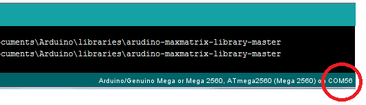
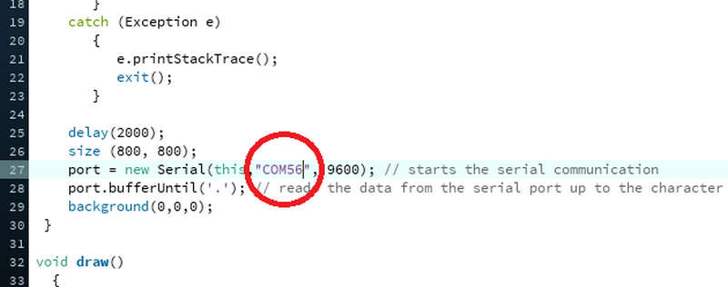
The Arduino code is as below: The Processing code can be downloaded from the code section below:
Conclusion:
With this, your DIY Joystick using accelerometer is ready! Now you can have double the fun playing your favorite games!


 1-37 screenshot")


