
Introduction
Eyes on the prize, Violet. Eyes on the prize!
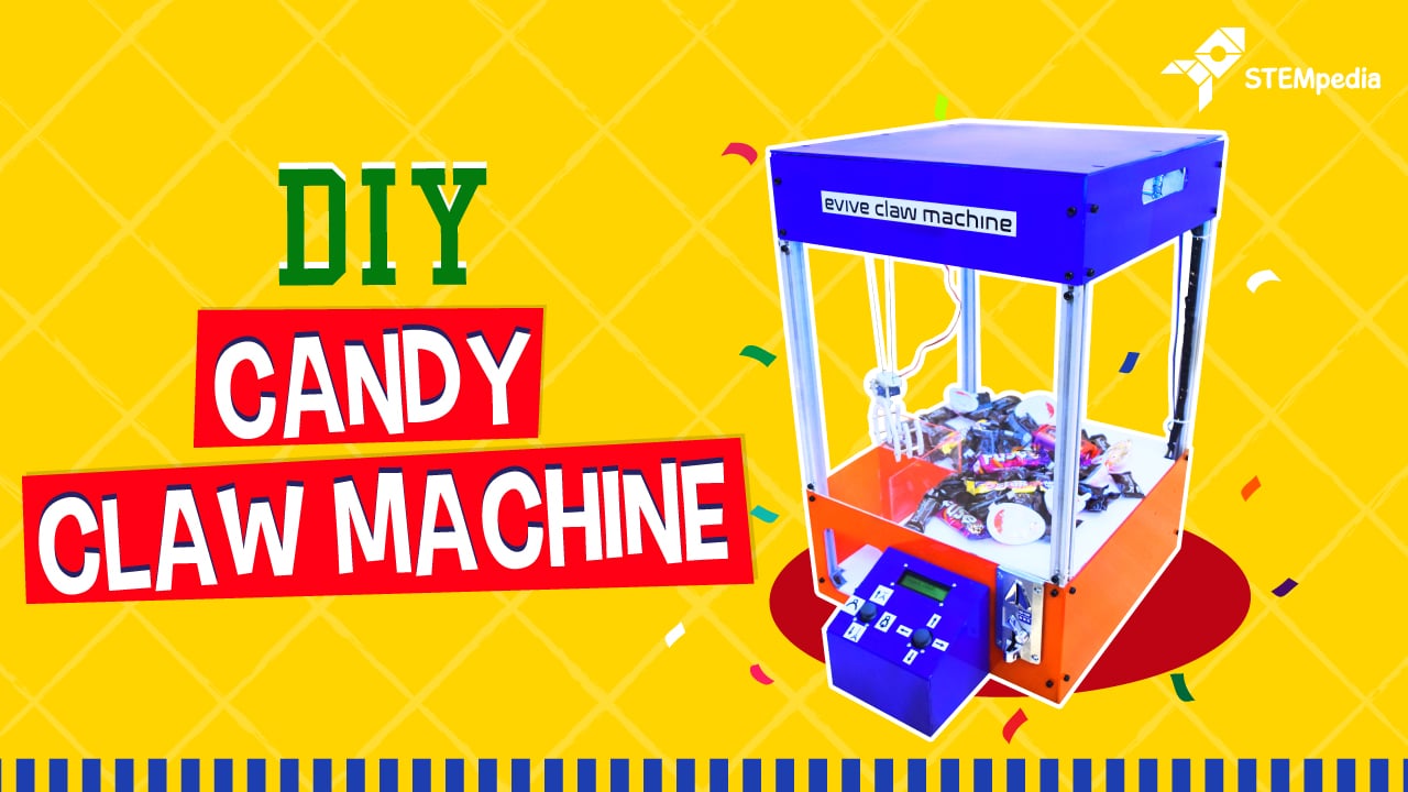
Get ready to challenge your friends and family to a candy hunt as we bring to you the classic arcade game – the candy claw machine – with the touch of DIY! You can now easily make your own DIY candy claw machine at your home and challenge your mates to a candy battle. Whoever gets the maximum number of candies wins!
The Candy Claw Machine is without fail going to add life to your party!
So, what are you waiting for? Hop right in before all the candies disappear!
A brief overview of Claw Machine
The working of the claw machine is simple:
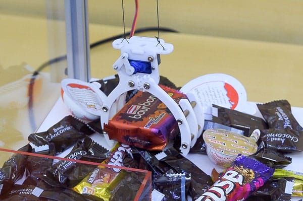
- The user can start the game by inserting a coin into the coin machine. After inserting the coin, the user gets 2 min time to control the gripper, catch as many candies and drop them into the left corner from where the user gets the candy out.
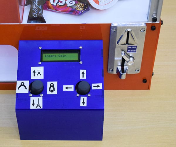
- The user can control the gripper open and closed position by moving the joystick left and right and move the gripper up and down, by moving the same joystick up and down. We have used a servo for gripper open and close mechanism and a motor, thread and a pulley to move the gripper up and down.
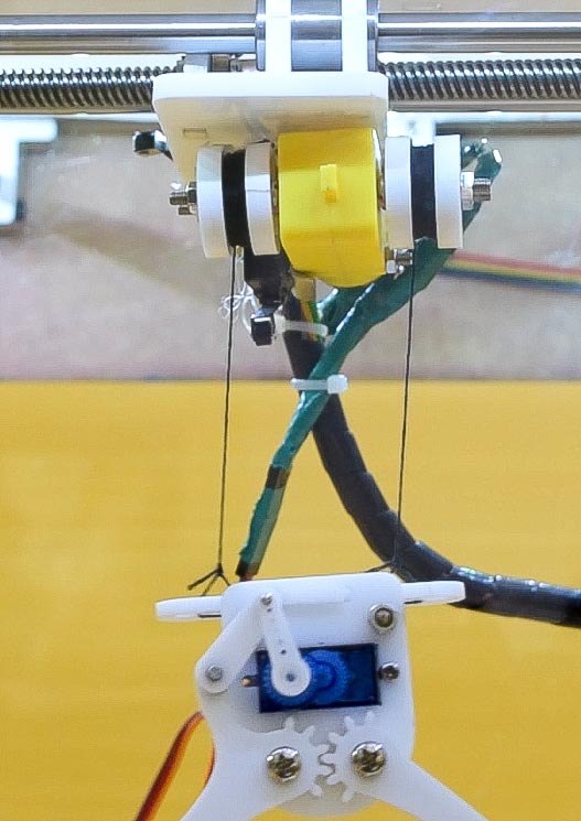
There is a limit switch on the top of the Gripper which prevents motor motion when gripper comes close to the Motor. - For the XY movement of the gripper, we have used the lead screw mechanism which is driven by stepper motors. To move the gripper in XY direction, the user uses the other joystick similar to gamepad controllers. There are also limit switches for X and Y directions to prevent any damage.
- The Claw making is decorated with RGB LED, which also tells the user about the time remaining.
- Green for start
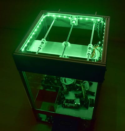
- Blue for 30 seconds over
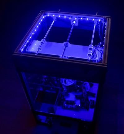
- Red for 30 seconds remaining
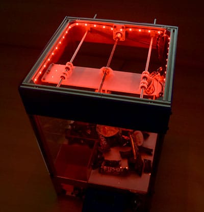
- Green for start
- For visual feedback, there is a 16×2 LCD displaying the instructions and the time remaining during the match.
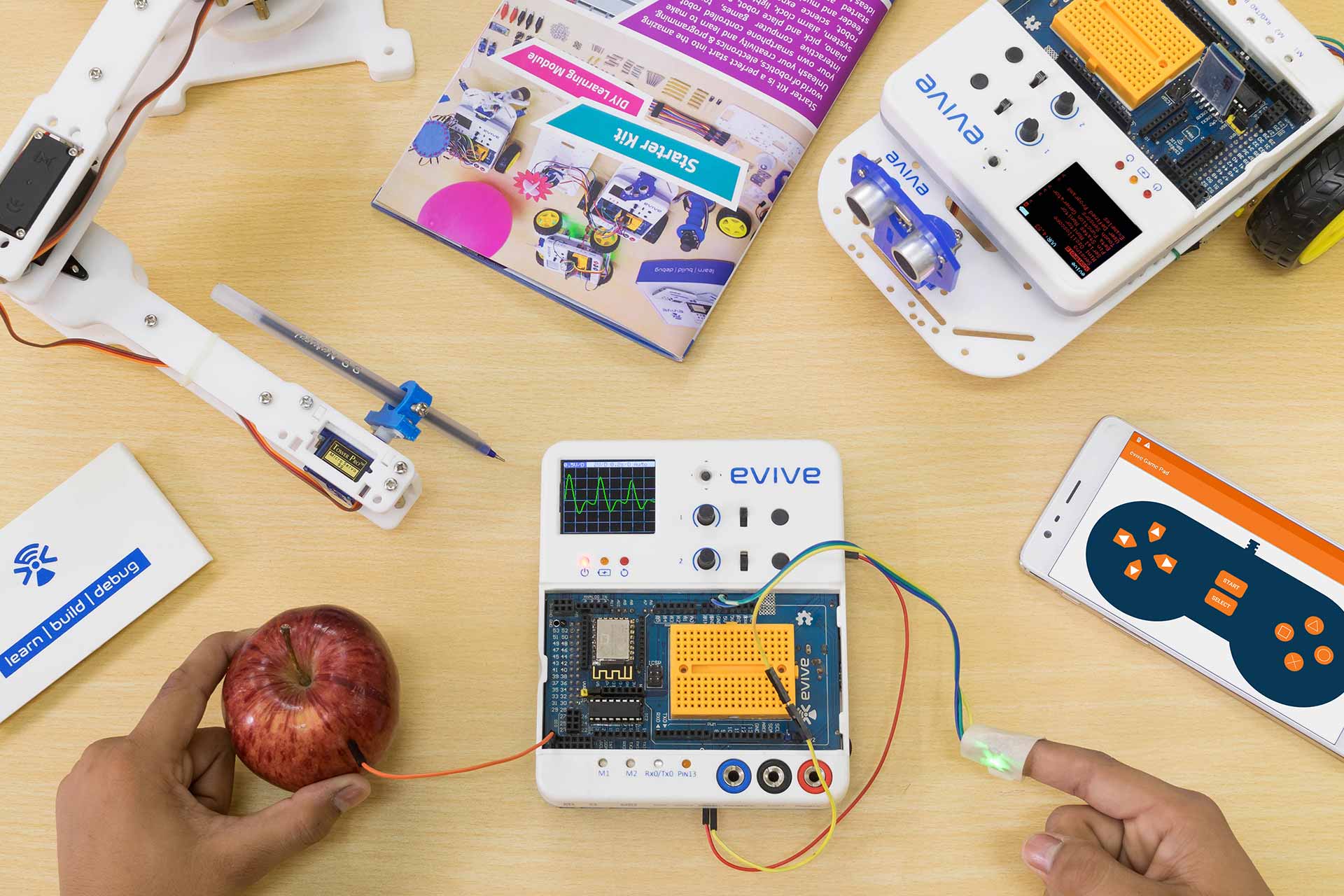
- All the electronics, sensors and actuators used in the project are controlled by evive.
- The frame of the candy claw machine is made using aluminum and acrylic sheet.
Building the Frame
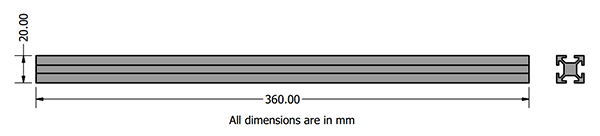
- The frame of the claw machine is build using Aluminium T Slot Extrusions to give it strength and stability. You have to cut the following lengths of the 2020 Aluminium Extrusion:
- Rod2020_1 590mm – 4
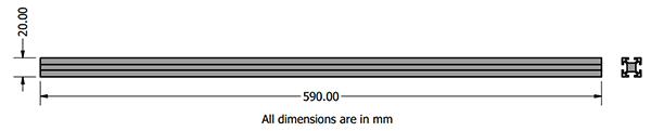
- Rod2020_2 400mm – 4
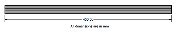
- Rod2020_3 360mm – 4
- Rod2020_1 590mm – 4
- After cutting the aluminum rods, we will assemble the base and the top of the frame first. For this, we will use 2 360mm rod and 2 400mm rod. Align the rods as shown in the diagram. Using the T Slot 2020 Aluminum Profile L-Shape Bracket mount the rods together.
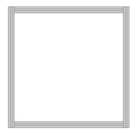
Now we have two square frames for top and bottom. - Next, mount the 560mm rods on the corner of the bottom frame as shown in the figure below using T Slot 2020 Aluminum Profile L-Shape Bracket.
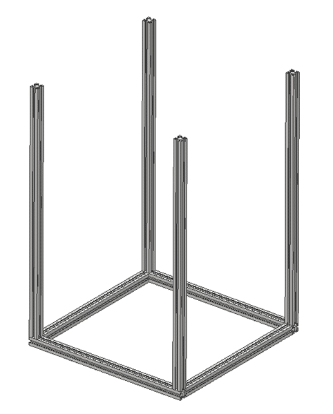
- Again mount the top of the frame on the verticle rods using the bracket.
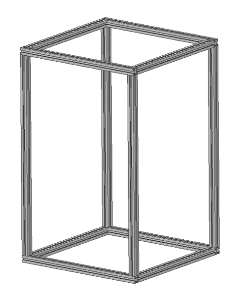
The frame is now ready.

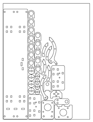
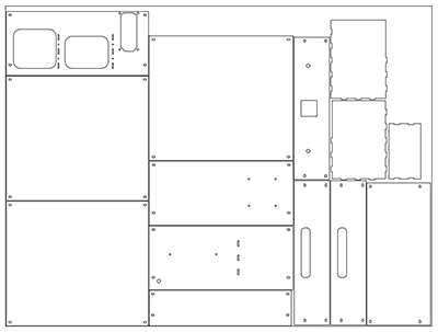
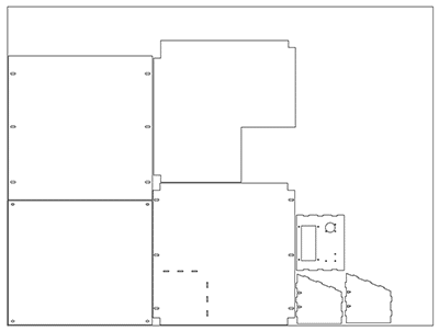
Cutting the Acrylic Parts
We will be using Acrylic Sheet for making the Acrylic Parts for various applications in the Claw Machine. We will cut the sheet using laser cutting machines.
- For 5mm parts, we will need a 400mm x 300mm sheet. You can download the files from here: 5mm_Acrylic_White_300mmx400mm
- For 3mm parts, we will need 2 1200mm x 900mm sheet. You can download the files from here: 3mm_Acrylic_White_1200mmx900mm & 3mm_Acrylic_White_1200mmx900mm2
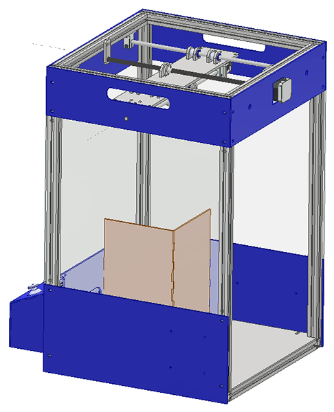
Assembling the Gripper Platform
The final gripper platform will look like this:
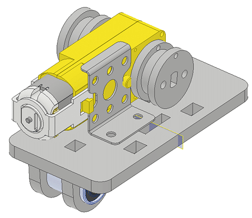
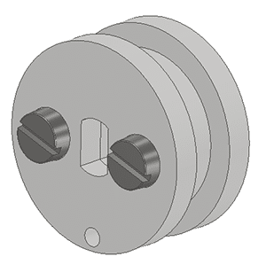
- First, assemble the pullies acrylic part to make a pulley like this:
- Next, attach the pulleys to each shaft of the BO Motor.
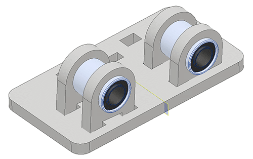
- Take the 2 bearing holders for the motor plate and glue both on the surface of the linear bearing as shown in the figure.
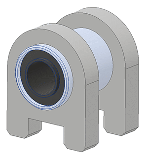
- Mount the bearing assembly just made on the Gripper plate using glue.
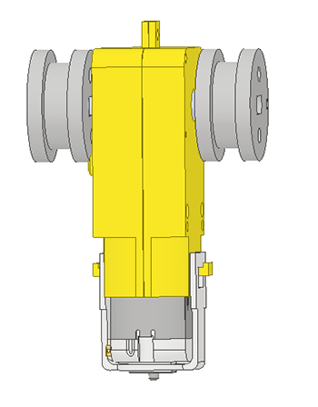
- On the opposite side mount the motor using the motor bracket.
- Finally, mount the Lead Screw Nut on the Gripper plate using Nut Holder.
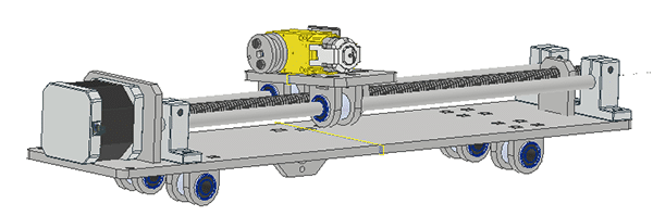
Assembling X Axis Movement Channel
The final subassembly will look like this:
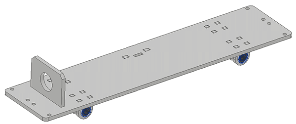
- Make for linear bearing holders and attach them to the X Channel Plate as shown in the figure.
- Also, mount the Y Channel Lead Screw Nut Holder on the same side.
- Mount the Stepper Holder for X Channel on the X Channel Plate.
- Mount the Stepper Motor to the holder using M3 Bolts.
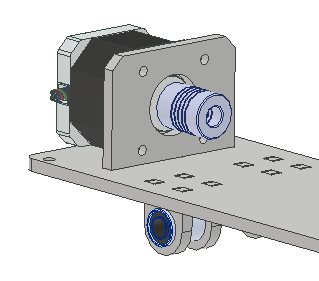
- Mount the Flex Coupler on the shaft of the Motor.
- Mount the Lead Screw shaft to the Flex Coupler.
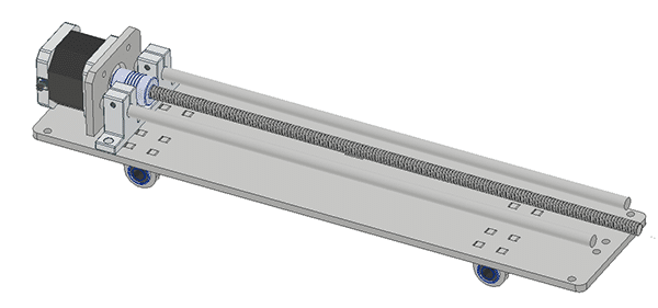
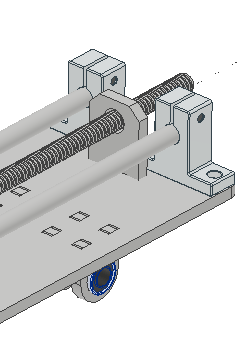
- Mount the 8mm End Shaft Holder on the sides of the Stepper Motor.
- Place the shaft on the End Shaft Holders.
- Slide the Gripper platform as shown in the figure:
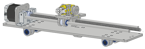
- Mount the other two End Shaft Supports on the other end of the X Channel Plate.
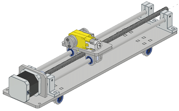
- Also Mount the Lead Screw Holder.
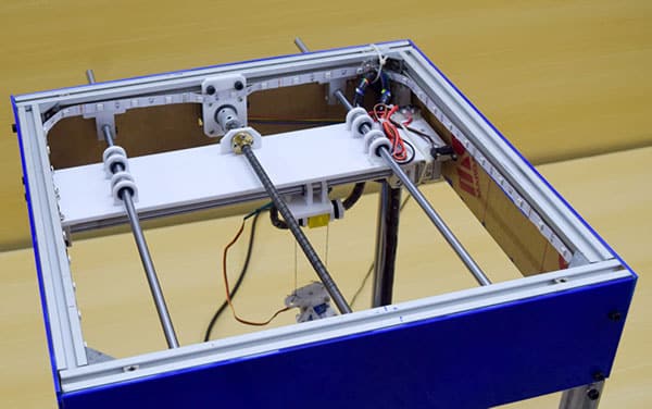
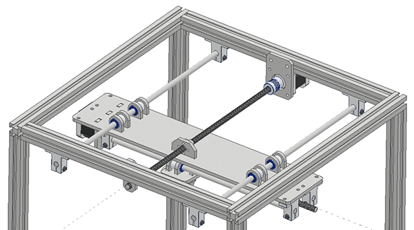
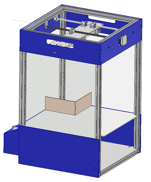
Assembling the Y Channel on Frame
The final subassembly will look like this:
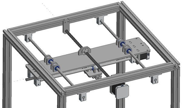
- Mount the Stepper Motor in the Y Channel Stepper holder and mount it on one of the sides of the top frame as shown in the figure below. Also, mount the flexible coupler on the stepper motor shaft.
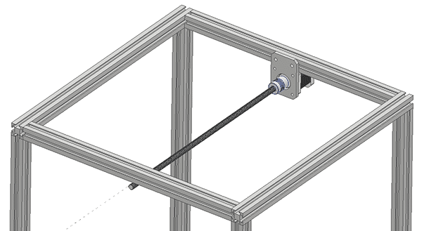
- On the same Aluminium Extrusion mount the End Shaft Support on both sides of the Stepper Motor.
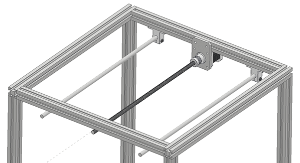
- Mount the 8mm rods and the lead screw rod on the End Shaft Support and the flex coupler respectively. Make the end shaft support and stepper motor holder flexible on the Aluminium Extrusion.
- Slide the X Channel Assembly on the rods.
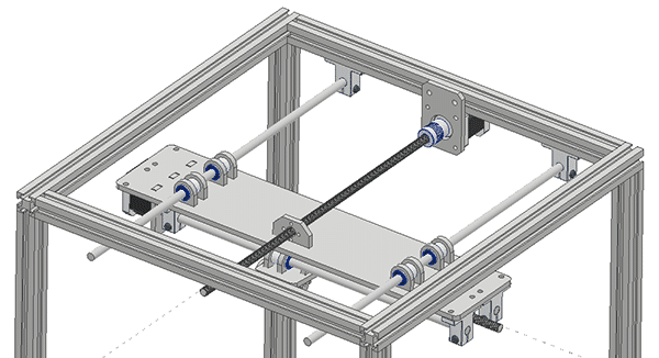
- Mount the End Shaft Supports on the other end of the shaft and the Lead Screw Holder.
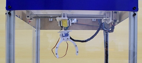
Assembling the Gripper
Assemble the Gripper as shown in the figure below.
Attach thread on the top plate of the gripper and the other end to the pulley as shown in the figure.
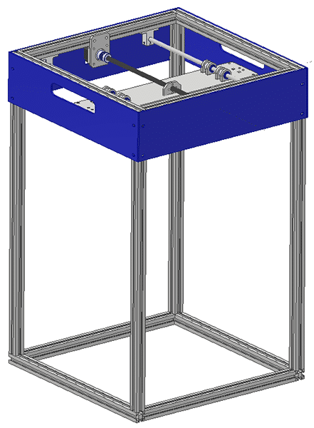
Mounting Acrylic Enclosure
- Attach the Top Covers First: Front, Back, and Sides using Allen bolts and T slot nuts.
- Attach the Base of the Claw Machine to the bottom of the frame.
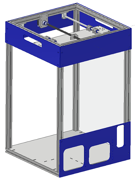
- Attach the Front Mid and the Front Bottom Acrylic Parts to the front side of the frame.
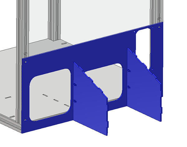
- Attach Controller Sides on the Front Bottom Acrylic Part using nut and bolts.
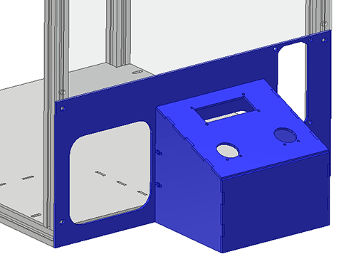
- Attach the Controller Top and the Controller Front on the Controller Side Plate.
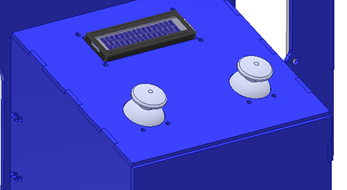
- You can now attach the Joystick Modules and the 16×2 Display Module on the Controller Top Plate.
- Mount the Left Middle SIde Plate and the Left Bottom Side Plate on the left side of the Claw Machine.
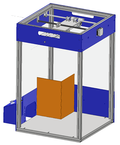
- Now attach the Barriers on the bottom Plate.
- Mount the Right Middle SIde Plate and the Right Bottom Side Plate on the right side of the Claw Machine.
- Mount the Candy Base Plate above the bottom plates.
Mounting the Coin Counting Machine
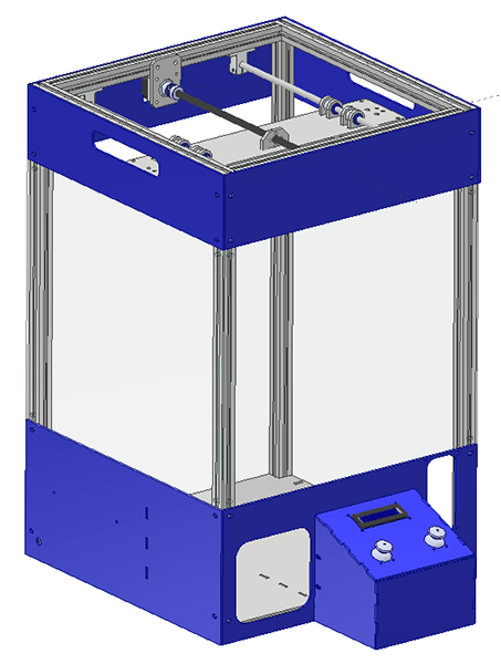
Mount the Coin Counting Machine on Front Bottom Plate using Nut and Bolts that come with it.
Mounting the Limit Switches
For Y-Axis, the Limit Switches are mounted in the X Channel Plate and when X Channel Plate goes near the Frame, the limit switch is pressed and motion stops.
For X-Axis, the Limit Switches are mounted in on the Gripper Plate, and when Gripper Plate goes near the Shaft Support Holders, the limit switch is pressed and motion stops.
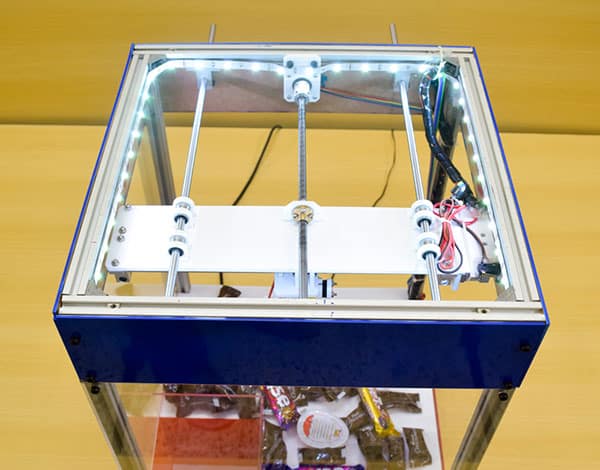
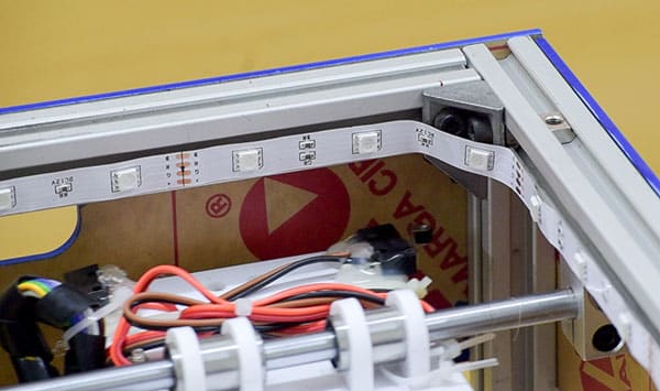
RGB LED Strip
The RGB LED Strip is mounted on the inner parameter of the top frame using Glue or Double Sided Tape. The wire is extended to reach the Bottom of the Claw Machine.
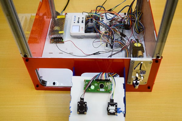
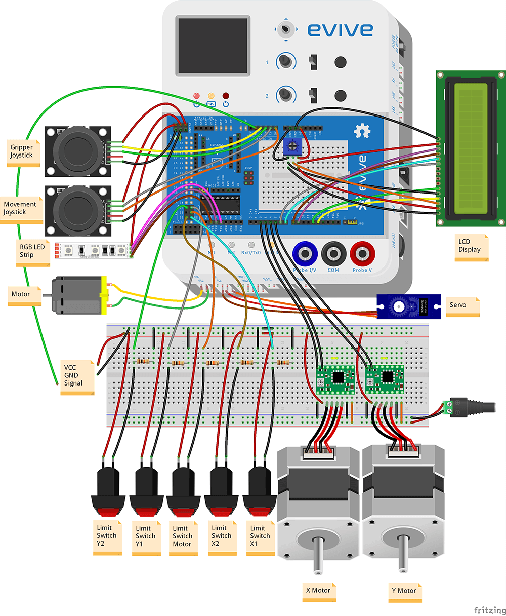
Circuit Diagram
We are using the following components that we have to connect with evive:
- Joystick – 2
- RGB LED Strip
- Motor to Motor Channel 1 of evive
- Servo to Servo Channel 2 of evive
- 5 Limit Switches with Pull Down Configuration
- 2 Stepper Motor
- 2 Stepper Motor Drivers A4988
- 1 1602 LCD Display
- Coin Detecting Machine
- 12V 5A Power Supply
Here is the Fritzing Diagram of the Circuit:

In real the circuit is very dense and messy, hence we used some wire management in the upper part of the claw machine.
Code
Following is the final code in Arduino IDE:
Conclusion
With this, your DIY Candy Claw Machine is ready. Challenge your friends to a candy grabbing duel and get as many candies as you can!


 For Construction Sites by Abhay Maheshwari 2-6 screenshot")


