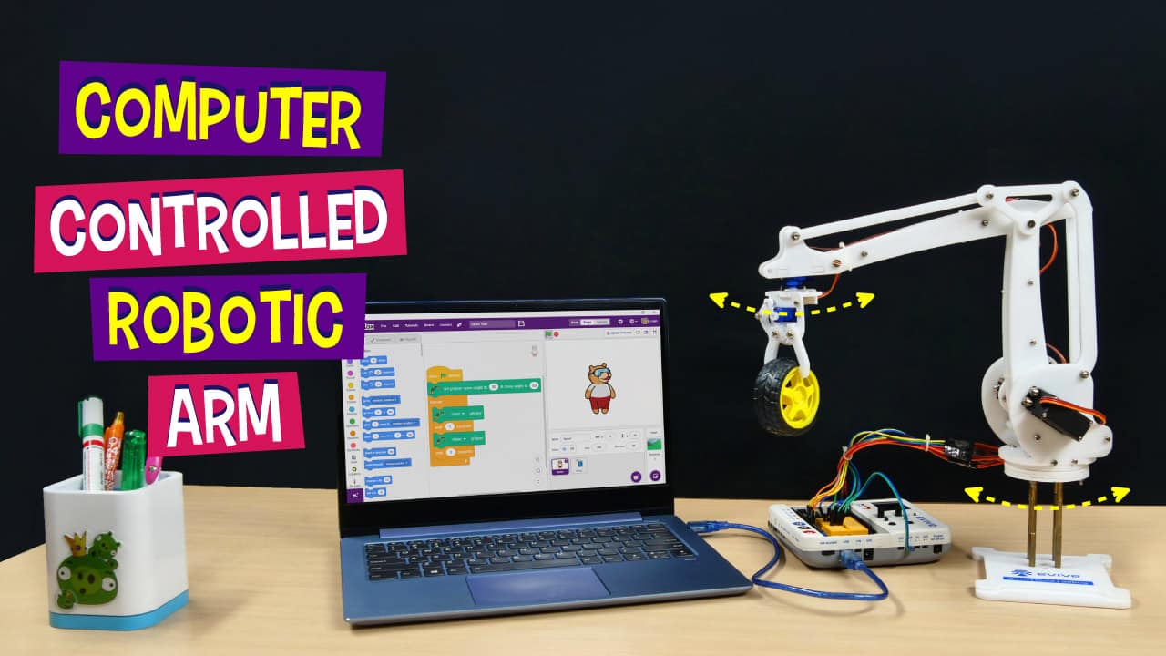

Introduction
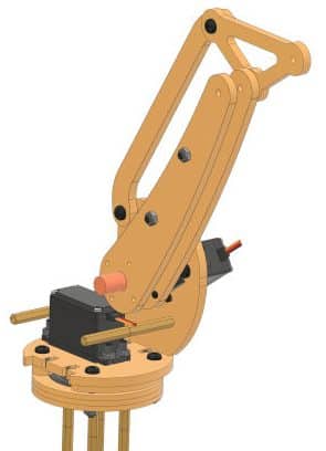
Get yourself an extra hand to help you out with moving stuff (at least on your table) with the DIY computer-controlled robotic arm. This 5 DoF robotic arm project is perfect for kids to take a sneak peek into the world of industrial robots and see how they work. You can easily build the pick and place robotic arm with the components available in the 5 DoF robotic arm kit and program it in PictoBlox – our Scratch blocks-based graphical programming software. Download PictoBlox from HERE.
Ready for some robotic arm action?
Let’s begin!
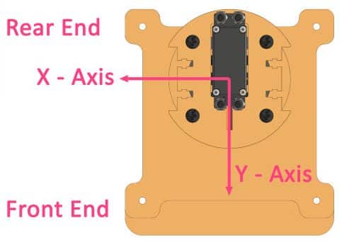
Making the Base of the Smartphone-Controlled Robotic Arm
Let’s start with the assembly.
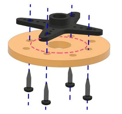
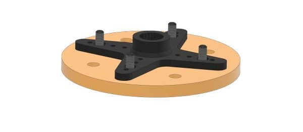
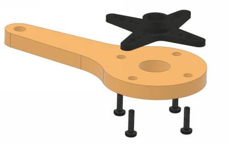
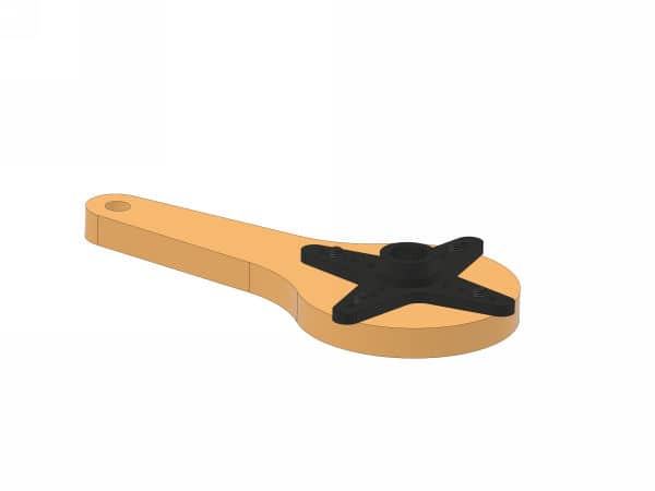
- Mount the servo horn on the Inner Bearing Disc using self-threading M2 screws found in metal servo accessories. Use the four holes which are closer to the center.
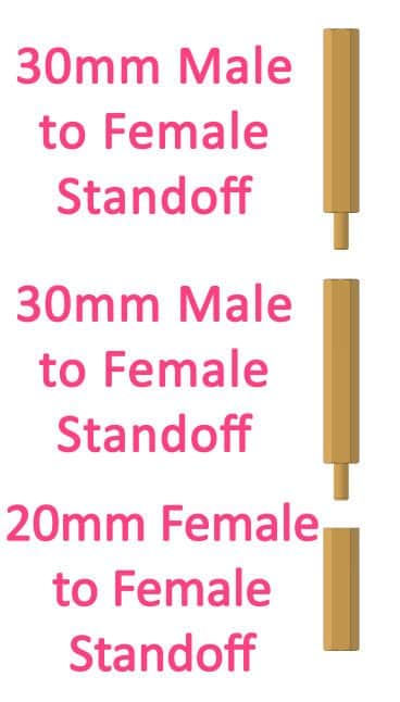
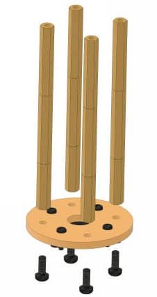
- Make an 80mm custom standoff using two 30mm male to female standoffs and one 20mm female to the female standoff. Similarly, make 3 more.
- Fasten these standoffs to the Inner Bearing Disc using M3 bolts of 8mm length. Make sure that you attach the standoffs on the side opposite to that of the servo horn.
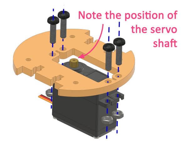
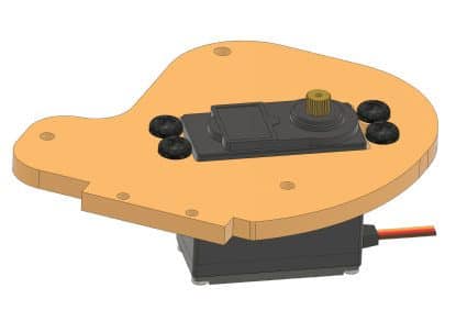
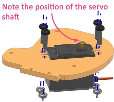
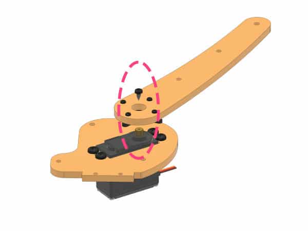
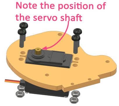
- Attach the Metal Servo to the Base Servo Motor Plate using M4 bolts of 16mm length and M4 nuts. Make sure that the servo shaft is at the center of the plate.
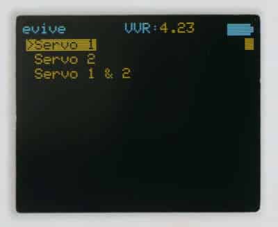
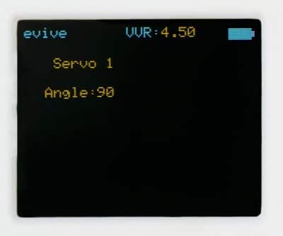
- Now, we need to set the servo angle to 90 degrees. For that, first, connect the Metal Servo to evive’s servo channel S1.
- Then, connect the Adapter and switch ON evive. Set VVR to 6V by rotating the VVR knob.
To set the angle, open evive’s menu and select Controls, then Servos, then Servo 1. Rotate the potentiometer1 of evive and set the servo angle to 90°.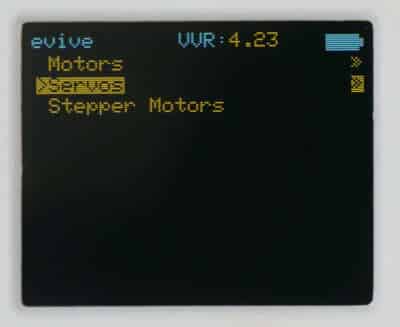
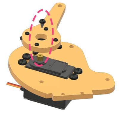
- Next, sandwich the Bottom Outer Bearing Disc, Bearing, two Middle Outer Bearing Disc, Top Outer Bearing Disc. and the Base Servo Motor Plate together.
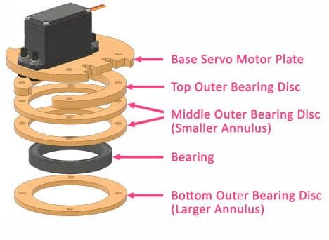
- Align the holes of the outer rings and hold them in place using four M4 bolts of 25mm length and M4 nut.
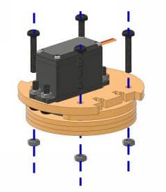
- Finally, lock the servo horn to the servo shaft using the servo screw. Make sure that the standoffs are aligned to outer bearing bolts.
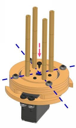
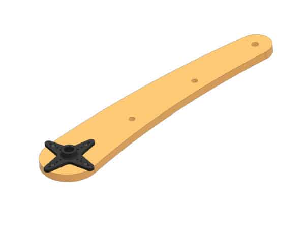
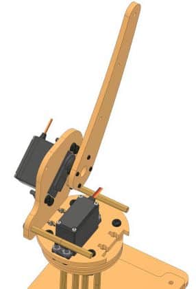
- Now, mount the other end of the standoffs to the Robotic Arm Base using M3 bolts of 8mm length. Make sure that the Base is mounted in such a way that the servo is closer to the rear end of the base.
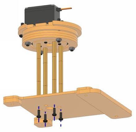


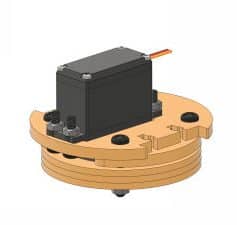
With this the base of the Robotic Arm is ready, our entire robotic arm assembly will be made on it.
Making the Left Side of the Robotic Arm
Now, that the base is ready, let’s make the left side of our Smartphone-Controlled Robot
- Mount another metal servo to the Side Servo Mounting Plate using M4 bolts of 16mm length and M4 nuts. Make sure that the servo shaft is nearer to the end.
- Set the servo angle to 45° as done before using the evive’s firmware.
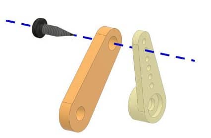
- Next, attach the servo horn to the Left Lower Arm using self-threading screws.
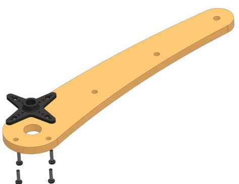
- Align and place the servo horn on the metal servo shaft and fix it using the servo screw.
- Make two custom standoffs of 60mm length by attaching male-to-female standoffs and female-to-female standoffs of 30mm length each and mount them on the left side Servo Mounting Plate using M3 Bolts of 8mm. The standoffs will be on the same side as the Left Lower Arm.
- Now, mount the left Side Servo Mounting Plate to the left side of the Base Servo Motor Plate using M3 bolts of length 12mm and M3 Nut
 .
. - Next, take the Left Middle Arm and attach it to the left Side Servo Mounting Plate using M4 bolt of 16mm length and M4 nut. Keep it loose enough for the arm to rotate freely.
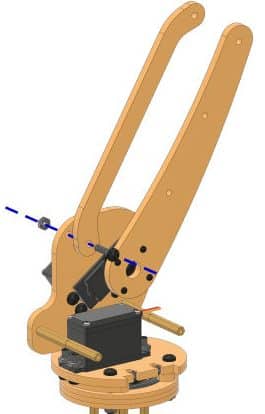
- Next, take the Triangular Junction Plate and mount the other end of the Left Middle Arm to it using M4 bolt of 16mm length and M4 Nut. Keep it loose enough for the arm to rotate freely.
- Now, take another Left Lower Arm and mount it to the first Left Lower Arm using M4 bolts of 25mm length and M4 nuts. Add two Spacers in-between the arms to maintain a 10mm distance.
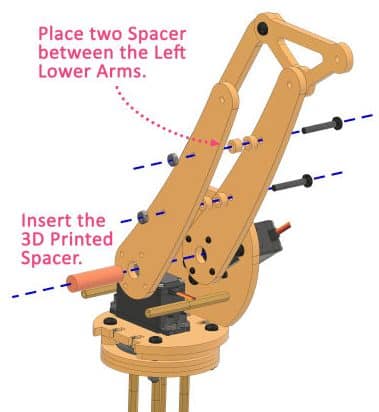
- Next, insert the 3D Printed Spacer in-between the Left Lower Arms.


With this, the left side of the robot arm is completed.
Making the Upper Arm Assembly
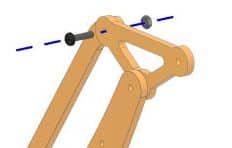
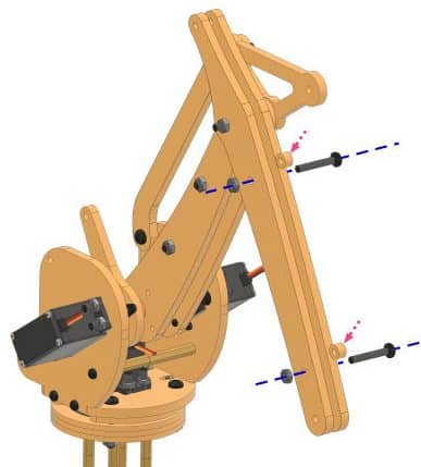
Take the two Right Upper Arms.
Next, bring together the Triangular Junction Plate’s center hole, Left Lower Arm’s top hole, Spacer, first Right Upper Arm’s second hole, Left Lower Arm’s top hole, second Right Upper Arm’s second hole and fasten them together using M4 bolt of 40mm length and M4 nut. Keep it loose enough for the arms to rotate freely.
Completing the Right Side of the Robotic Arm
Now, let’s complete the other half of the Robotic Arm i.e. the Right Side.
- Now, take the right side Servo Mounting Plate and attach another Metal Servo on it using M4 bolts of 16mm length and M4 nuts.
- Set the servo angle to 90° using evive’s firmware. Make sure that the servo shaft is closer to the rear end.
- Next, take the Right Lower Arm and attach the metal servo horn to it using servo screws.
- Then, attach the servo horn to the servo shaft using the servo screw.
- Next, fasten the right side Servo Mounting Plate to the Base Servo Motor Plate using M3 bolts of 12mm length and M3 nuts.
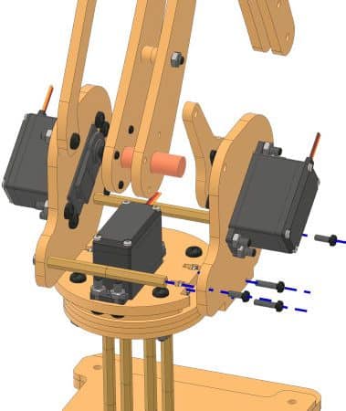
- Then, attach the Side Servo Mounting Plate to the 60mm length Standoff using M3 bolts of 8mm length.
- Next, fix the two Right Upper Arms together with the Spacers sandwiched in between using M4 bolts of 25mm length and M4 nut.
- Now, take the Right Middle Arm and fasten it to the Right Lower Arm using M4 bolt of 16mm length and M4 nut on one side.
- Then, attach the other end of the Right Middle Arm to the Right Upper Arm using M4 bolt of 40mm length and M4 nut. Add three spacers in-between to maintain a proper distance. Keep it loose enough for the arms to rotate freely.
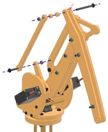
- Attach the Left Upper Arm to the third hole to the Triangular Junction Plate using M4 bolt of 16mm length and M4 nut. Keep it loose enough for the arms to rotate freely.
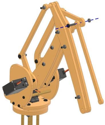


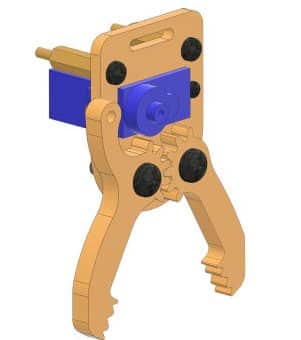
Yay! With this, the assembly of the robotic arm is almost ready. All we need to add is the pick and place mechanism. So that the robot arm can pick any object and place it where we guide it to.
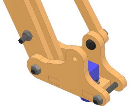
Making the Gripper Assembly
Our Computer Controlled Robotic Arm is also capable to lift and drop things. Thus, it’s time to turn our normal robotic arm into the Pick and Place Robotic Arm by adding the gripper assembly to it.
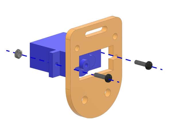
- Take the End-Effector Rotational Micro Servo Plate and attach a micro servo to it using M2 bolts of 12mm length and M2 nuts.
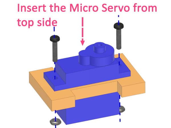
- Set the servo angle to 90° using evive’s firmware as done before.
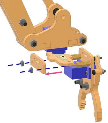
- Mount a Rotational Servo Plate to the Left Upper Arm using an M4 bolt of 16mm length and M4 nut. Keep it loose enough for the arms to rotate freely.
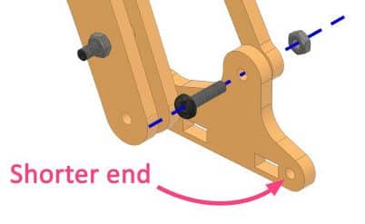
- Fix the End-Effector Rotational Micro Servo Plate inside the rectangular slot of the Rotational Servo Plate. Make sure that the servo head faces downward.
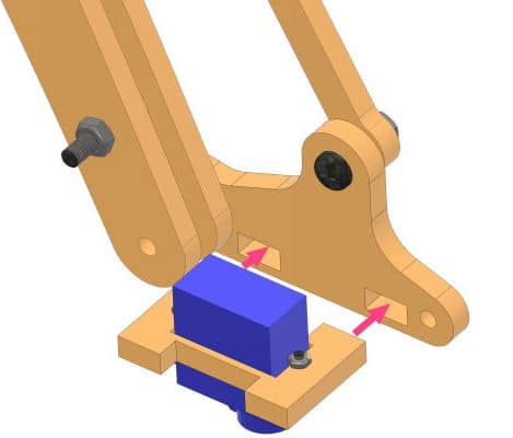
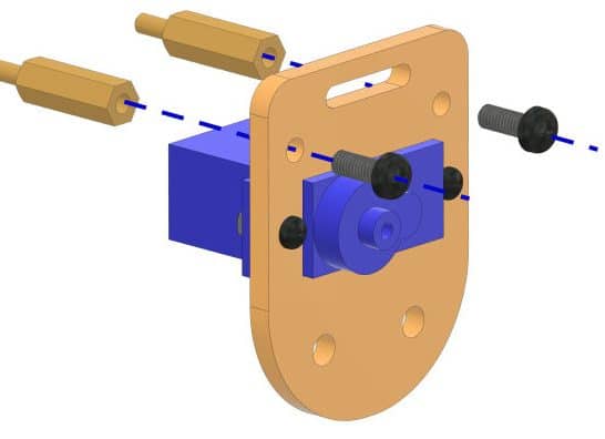
- Take another Rotational Servo Plate and attach it to the other side of the End-Effector Rotational Micro Servo Plate using M4 bolts of 30mm length and M4 nuts. insert a spacer between the two Right Upper Arms. Keep it loose enough for the arm to rotate freely.
- Next, insert the micro servo in the slot on the Gripper Part 1 and fasten it using M2 bolts of 12mm length and M2 nuts.
- Set the servo angle to 30° using evive’s firmware.
- Attach two M3 Standoff of 15mm length to the Gripper Part 1 using M3 bolts of 8mm length.
- Take Gripper Claw 1 and Gripper Claw 2 and attach them to the Gripper Plate 1 using M4 bolts of 16mm length and M4 nuts. Make sure that the Gripper Claw 1 is near the servo shaft and the gears of the claw perfectly fit together and are symmetric. Keep the bolts loose.
- Now, take the Gripper Link and attach a micro servo single-sided horn to it using self-threading screws. Keep it loose enough so that they can rotate freely.
- Take the Gripper Claw 1 and attach the other end of the Gripper Link to it using an M3 bolt of 12mm length and M3 nut. Keep it loose enough for the claw to rotate freely.
- Open the gripper claw by moving the Gripper Claw 1 and Gripper Claw 2 apart and then fix the micro servo horn to the micro servo’s shaft.
- Finally, mount the servo screw on the micro servo horn to secure it.
- Now, take a Gripper Plate and attach a dual-sided micro servo horn to it using self-threading screws
- Fix the servo horn to the rotational servo’s shaft using a servo screw. Make sure the Gripper Plate is perpendicular to the micro servo.
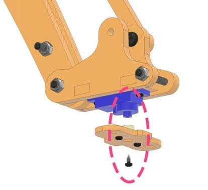
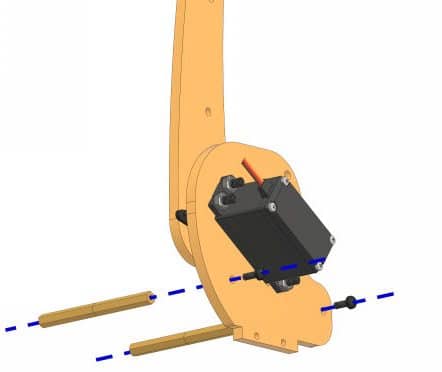
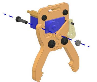
- Finally, take the gripper assembly and fix it on the Gripper Plate. On the other side of the Gripper Plate attach the Gripper Part 2 such that the standoffs align to the holes and fix it using M3 nuts.


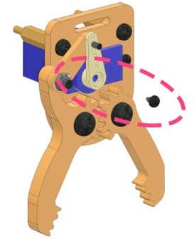
In case any of the M4 nuts come out or become loose during the assembly, use M4 Lock Nuts in their place at the joints.
With this the assembly of the Robotic Arm is complete.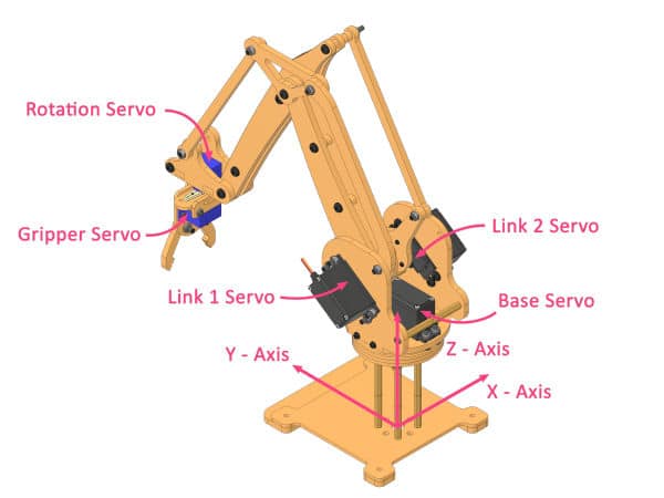
Making the Connections
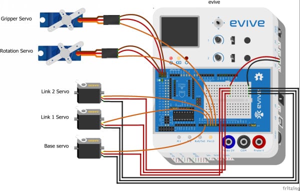
Now let’s move on to the circuitry. We are going to use evive as the brain to control our robotic arm.
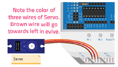
Before connecting the servos to the evive, extend the wires of all the servos.
- Next, make the connection of metal servo as below:
- Connect the VCC and GND of the Base, Link 1, and Link 2 servo to the breadboard as we are going to make the VCC and GND of them common.
- Connect Signal Pin as:
- Base Servo – Digital Pin 2 of evive.
- Link 1 – Digital Pin 3 of evive.
- Link 2 – Digital Pin 4 of evive.
- Now, let’s connect the remaining two micro servos.
- Connect VCC and GND of both the micro servo to the +5V pin and GND pin of evive.
- Connect Signal Pin as:
- Rotational Servo – Digital Pin 5 of evive.
- Gripper Servo – Digital Pin 6 of evive.
Now, connect the positive terminal of the VVR pin to the VCC column and the negative terminal to the GND column.
The complete circuit will look like this. 
Now, it’s time to power up the evive. Connect the 12V adapter to evive and switch it ON by sliding the power switch to EXT. Set the VVR to 6V by rotating the VVR knob. As higher voltage may damage your servo.
With this, the connections are complete.
Calibrating the Robotic Arm
Time to calibrate our robot arm. We are going to use PictoBlox for the same.
- Open PictoBlox. Connect evive to the computer using the USB cable.
- Click on the board and select evive and then select the appropriate port.

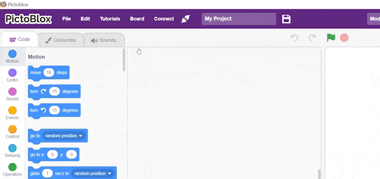
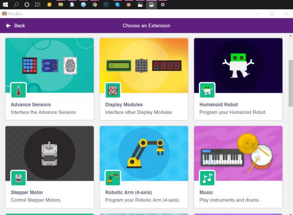
- Now, click on the Add Extension button and add the Robotic Arm extension from the list.
- As we need to calibrate the robotic arm in real-time i.e. the Stage Mode, we first need to upload the stage mode firmware to it. Create a script with when evive starts up as the hat block and snap the upload stage mode firmware block below it.

- Switch to Upload mode by toggling the mode button.
- Then, click on the Upload Code button.
- Once uploaded successfully, switch back to the Stage Mode.
Now, let’s create the script for calibration.
- Drag and drop the when flag clicked hat block.
- Next, drag and drop the Connect servos – base () link 1 () link 2 () rotational () gripper () block. It will define the PWM pins to which each of the servos are connected.

- Then, drag and drop the Set offset along length () & Z () block. It will add the offset on the end effector position along the specified length direction and the Z direction.

- Next, drag and drop the Calibrate angles – base () link 1 () link 2 () rotational () gripper () block for calibrating the angles of the servo motor and save them in evive’s memory.

- Finally, drag and drop the Go to X () Y () Z () in () ms block. It will move the robotic arm end-effector to the specified X, Y and Z position in the specified time.

- Click on the green flag to run the script.
Calibrating the Base Servo:
If the robotic arm is not straight, then change the base offset angle and run the script. Use the trial and error method to calibrate the servos.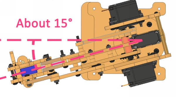
Calibrating the Rotational Servo:
If the rotational servo is not in the center, try changing the rotational angle in the calibrate angles block.
Calibrating the Link 1 and Link 2 Servos:
Now, let’s calibrate the Link 1 Servo and Link 2 Servo.
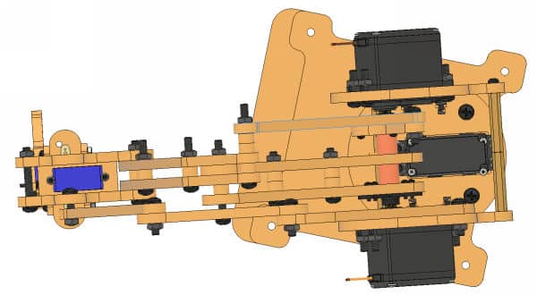
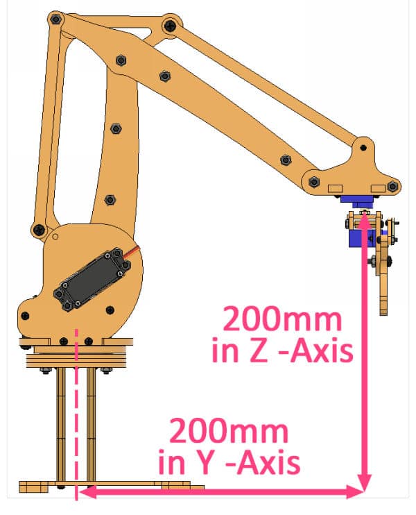
Using a scale, measure the distance of the end effector from the head of Rotational Servo to the base center in the Y and Z direction. If it is 200mm in both directions, then it’s ok; otherwise, change the link 1 and link 2 angles in the calibrate angles block, so that the distance is 200mm along both the axes.

Run the script every time you calibrate a part.
Finding Gripper Opening and Closing Value:
Now, let’s get the opening and closing value of gripper.
- For that, let’s write a small script.
- Drag and drop a when flag clicked hat block into the scripting area.
- To run the code continuously, use the forever block.
- First, using the set () servo angle to () in () ms, set the angle of the gripper servo to the value obtained by rotating potentiometer 1.
- Next, make a variable named Gripper Angle to save the current angle of the servo.
- Finally, set the value of the Gripper Angle variable to the gripper servo angle using get current () servo angle block.
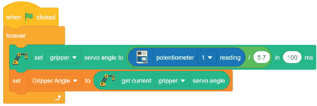
- Now, run the script.
Note the value of Gripper Open Angle and Gripper Close Angle using potentiometer 1.
With this, the calibration of the robotic arm is complete.
Making it Computer-Controlled Robotic Arm
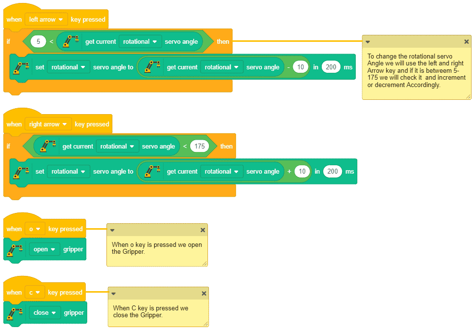
Now, we are going to make a manually controlled pick and place robot using the keys of your computer. Write the code for the same.
Create the script to initialize the robotic arm when the flag is clicked.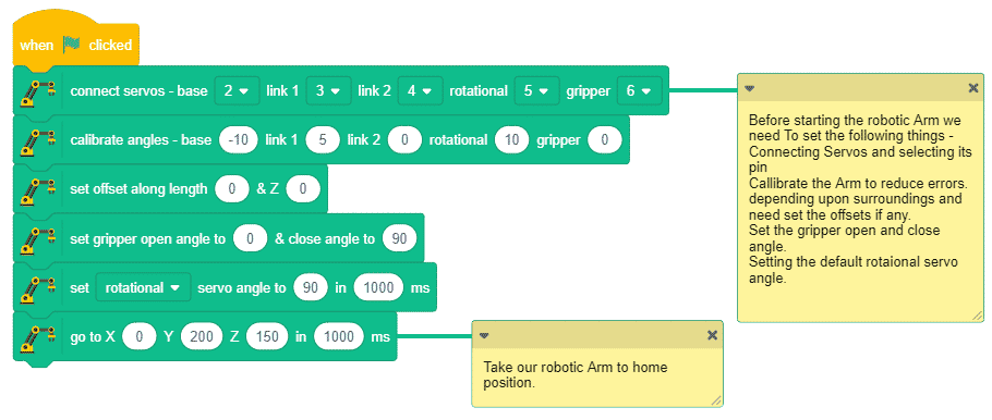
Following are the controls for the robotic arm: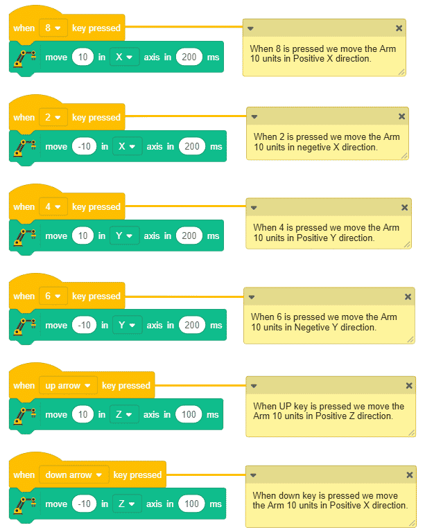
Conclusion
With this, your DIY computer-controlled robotic arm is ready!