
Introduction
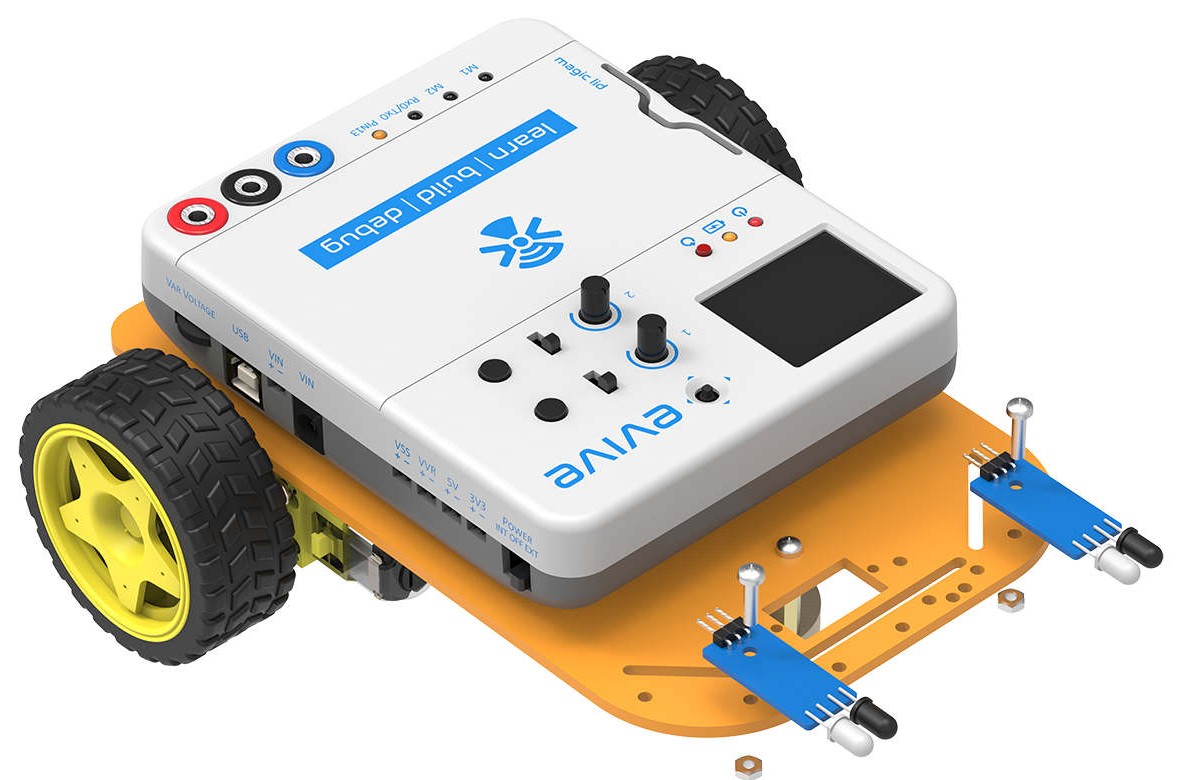
We will move forward and design our first autonomous robot. This robot will follow any object coming in front of it within a range of 5-10 cm. We will be using two IR sensors (proximity sensors), which will detect objects in front of them and send a signal to the robot. Both sensors will be attached in the front of the robot, one on the left side and one on the right side.
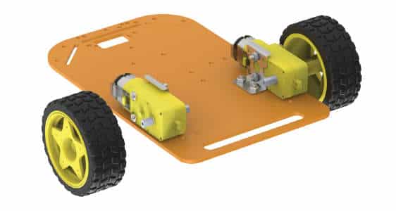
Assembly
The annotated base is shown on right. This is the bottom side. There is the evive logo on the top side for your reference. So be careful while using the base.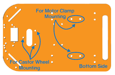
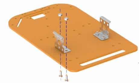
- Fix the motor mounting brackets to the chassis using M3 bolts of 8mm length and M3 nuts.

- Attach the two motors, one to each bracket, side by side and fasten using M3 bolts of 25mm length and M3 nuts.
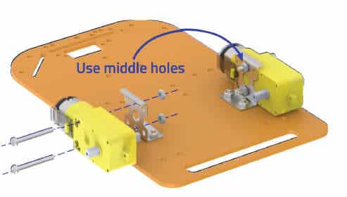
- Now, fit the wheels into the protruding motor shafts.
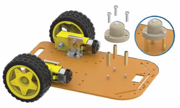
- We’ll attach the Castor wheel now. First, we will mount the M3 standoffs (20 mm) on which the Castor will be attached. Fasten the standoffs to the chassis using M3 bolts of 8mm length.
- Place the Castor on top of the standoffs in the configuration shown and fasten using M3 bolts of 12 mm length.

- Flip the assembly and place evive on the top of the chassis.
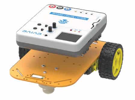
- Using the holes on the back of evive fasten it to the chassis using M3 bolts of 12mm length.
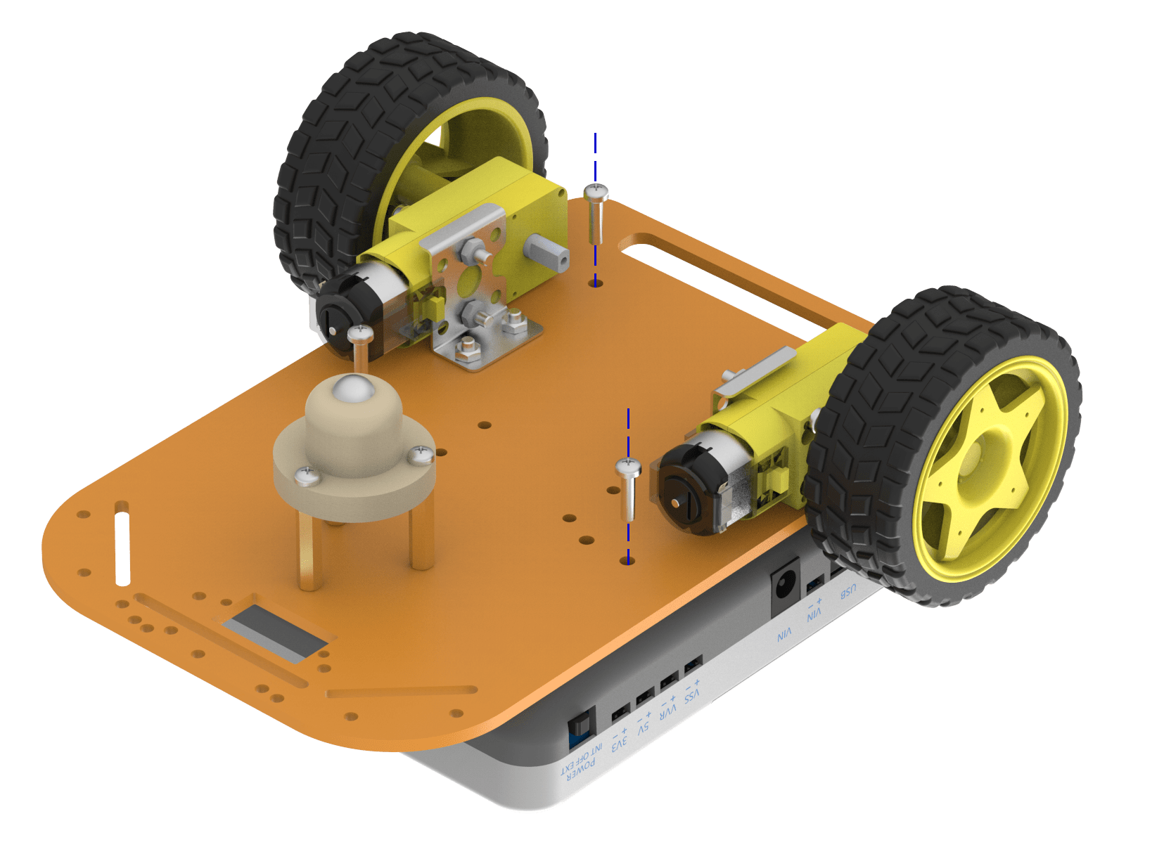
- We will now attach 2 IR sensors onto the front of the robot.
- Screw the sensors onto the top side of the base as shown in the figure above using an M3 bolt of 12mm length and M3 nuts.
Circuitry of the Robot
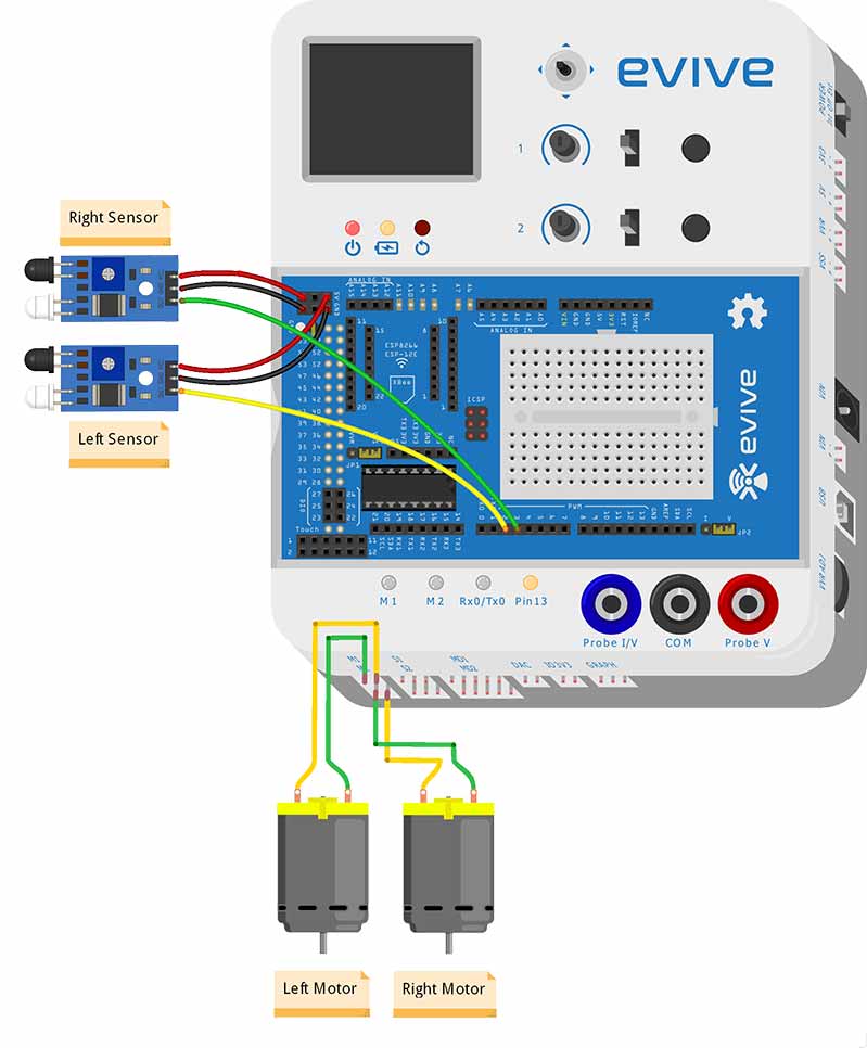
Connect the motors and IR sensor wires as shown in the figure on the next page. Be careful while connecting the IR sensors (Note that VCC is 5V).
Calibrating IR Sensor
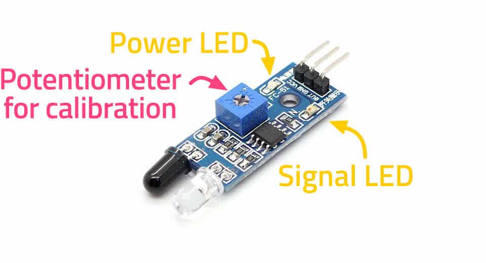
We are using an IR sensor to detect objects in front of the robot. An IR sensor has two small LED indicators. One is for power, which is ON all the time, the sensor is powered. The other LED is the signal LED which tells whether there is an object in front of it or not. There are two states for the sensor:
- Signal LED is ON (Active): When the sensor detects the object in front of it.
- Signal LED is OFF (Inactive): When the sensor does not detect the object.
 We have to calibrate both the sensors, such that it can detect the object in front of it.
To calibrate your sensor, switch ON your evive. Keep everything at least 15 cm away from the sensors. If the signal LED is OFF, then your sensor is OK for now, otherwise gently turn the potentiometer knob on the sensor in anti-clockwise direction using a screwdriver, such that the LED turns OFF.
Place an object in front of the sensor at about 5cm. The signal LED should turn ON. If it is not ON, gently turn the potentiometer in a clockwise direction, such that the LED turns ON when the object is in front of it and stays OFF otherwise.
Logic and Flowchart
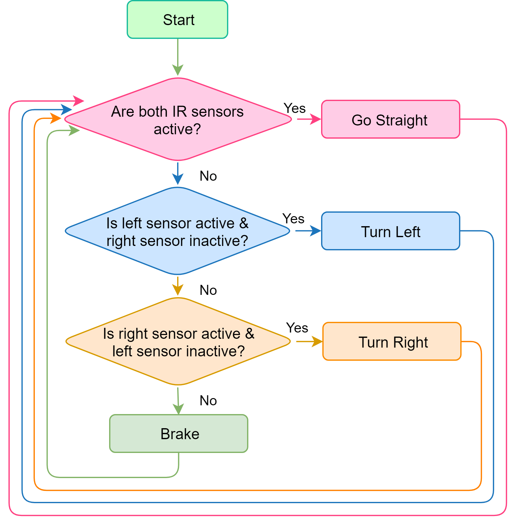
Our robot can execute four actions:
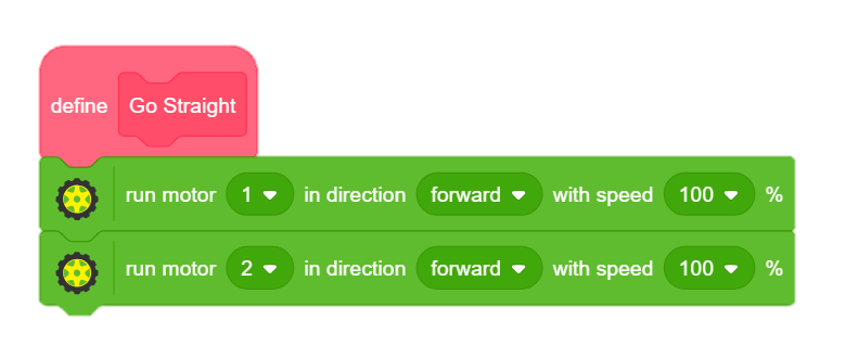
- Go Straight
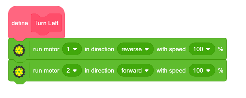
- Turn Left
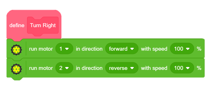
- Turn Right
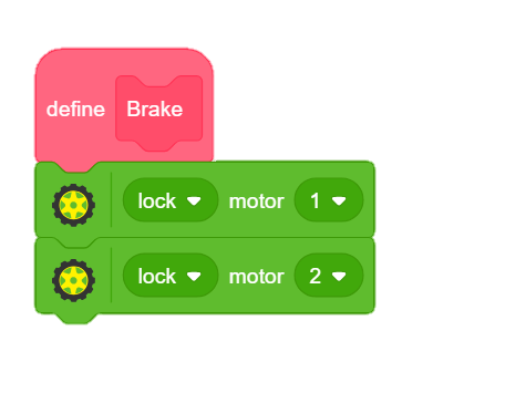
- Stop or Brake
Now, we have to decide how to make the robot follow any object. This will depend on the state of both the IR sensors.
If both the sensors are active (object in front), then the robot should move forward to follow the object. If only the left sensor is active (object on the left), then the robot should turn left. If only the right sensor is active (object on the right), then the robot should turn right. If both the sensors are inactive, the robot should be stopped (brake).
Scratch Script
We are now going to create Scratch Scripts to generate code.
We will be writing the code in PictoBlox.
- Create blocks GoStraight, TurnRight, TurnLeft and Brake.
- Select the Upload mode from menu bar. Then, select evive as your Board and load the evive, Actuators, and Display extensions.
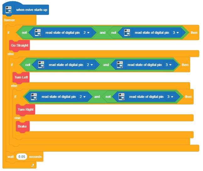
- Drag and drop the evive starts up hat block into the scripting area. Drag and drop the forever block below it.
- We will use if-else block to define actions depending on the state of both the sensors. Drag and drop an if-else block inside forever block. First, we will check if both sensors are active. We will use the not and and block from the operator palette for the same. Below the if arm, place the Go Straight block. Below the else arm, place another if-else block to check for further conditions.
- In the second if-else block, we will check if only the left sensor is active. If the condition is true, the robot must turn left. For that, drag and drop the Turn Left block below the if arm. Drag and drop another if-else block below the else arm.
- Now, we will check if only the right sensor is active. If this condition is true, the robot must turn right. For that, drag and drop the Turn Right block below this if arm. If none of the above conditions is true, the robot must stop. For that, drag and drop Brake block below the else arm.
- Finally, snap a wait block with 0.05 secs value at the end of forever block to make the robot stable. The script is ready and you can directly upload it to evive.
Your robot is ready to follow you everywhere and anywhere you like!
Debugging the Robot
At times, your robot will refuse to behave the way you are commanding it to. Let’s fix this. If upon pressing forward, your robot starts moving backwards or starts turning, that means at least one motor is rotating in the wrong direction. You can fix this by reversing the direction of that motor.
Your forward-backwards controls shall now work perfectly. If the robot turns left upon pressing left and right upon pressing right, your robot is good to go. If it turns right upon pressing left, you can fix this by exchanging wires of both the motors. Ask an elder for help, if you need.
Conclusion
With this, your new age pet is all set to accompany you wherever you go!


.mp4.00_00_00_00.Still001-c58cec4c")


