
Introduction
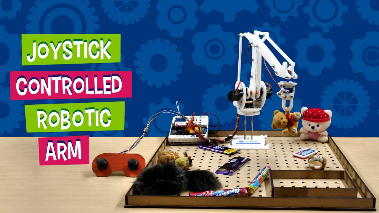
In the third edition of “having fun with robotic arms”, we’re going to show you how to make a joystick-controlled robotic arm and turn it into a DIY claw machine that you can have loads of fun with along with your chums! Everything that you need to make the robotic arm-cum-claw machine is available in the Robotic Arm Kit. Like the previous versions, you code this one with ease as well all thanks to PictoBlox, our graphical programming software based on Scratch blocks. Download PictoBlox from HERE.
Get your DIY arsenal ready ‘cause we’re beginning in 3, 2, 1… NOW!
Getting the Controller Ready
All of you must be familiar with the Robotic Arm. If not, to know how to make the robotic arm from the Scratch, make its connections with the prototyping board, calibrating it and to know how to simply control it using the keys of your keyword visit here.
If you have already made the robotic arm and want to make it an automatic pick and place robot so that it automatically sorts the objects based on the color. click here.
Now as we are going to make the Joystick-controlled, we first need to make the controller.
Take the printout of the controller and cut it out. You can even paint it if you want to bring out the Da Vinci in you.
Next, to make the controller sturdy, take a corrugated sheet and paste the controller’s image onto it. Now, cut along the controller’s shape on the corrugated shape.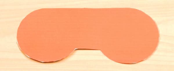
With this, the basic structure of the robotic arm is ready.
To do next, make it joystick-controlled.
Converting it into a Joystick Controller
As we have already made the base of our controller, we now need to make it a joystick-controlled robot.
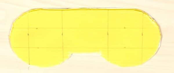
- Take the controller you have made in the previous step and leaving 2 cms from the bottom edge and the side, draw two rectangles of size 2 cm x 2.5 cm.
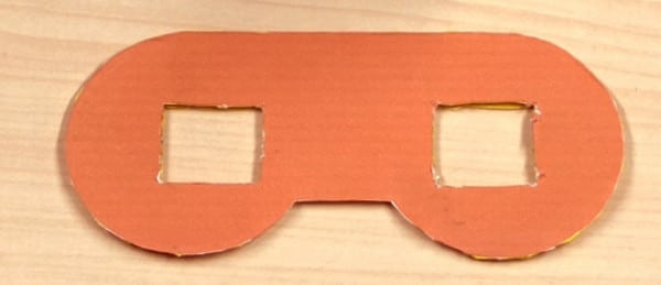
- Next, take the cut out of the rectangle. These holes are to house or fit our joystick in.
- Take two joysticks and remove their caps by pulling them off their headers gently.
- Next, insert the joysticks in the holes from below.
- Then, place the caps on the headers again from the top.
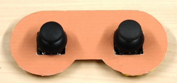
 Make sure that the joysticks should face upwards.
 - Fix the joysticks to the holes using Hot Glue.

Setting Up the Stage for the Claw Machine
Now, that the joystick controller is ready, we need to convert our stage area into a claw machine.
Firstly, we will add a small gift drop-off area, where we will drop our prizes after we grab it using our gripper arm.
Once done, fill the board with gifts and treats of your choice and start playing!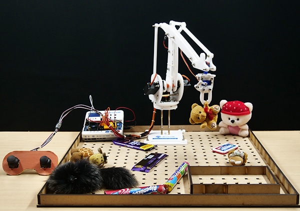
Connecting the Joysticks to evive
The Connection of the basic Robotic Arm remains the same. Thus, first, complete the connection of the normal pick and place robotic arm.
Connect the Jumper cables to both the Joysticks and extend them.
Firstly take two male to male jumper cables and connect the +5V and GND on evive to breadboard on the evive. This to make the +5V and GND of both the sensors common.
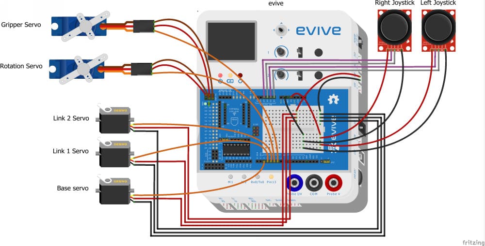
Now let’s do the connection for the Joysticks:
- Connect VRy of Joystick 1 to A0 pin.
- Connect VRx of Joystick 1 to A1 pin.
- Connect VRy of Joystick 2 to A2 pin.
- Connect VRx of Joystick 2 to A3 pin.
The Joystick on the left is Joystick 1 and on the right one is the Joystick 2.Writing the PictoBlox Code
To make the project simpler, we’ll write the script using PictoBlox. Before, writing the script, let’s first add the robotic arm extension.
As the joystick gives us two values, one for X-direction and one for the Y-direction. As we are using two joysticks, we will be getting 4 values, thus we will first make a default block for reading the input values from the joysticks and then storing them into the variable.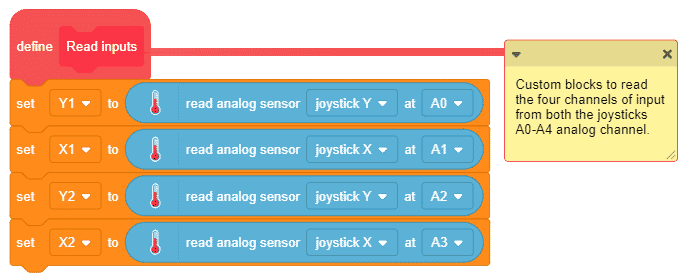
Now, every time you switch ON your board, we need the robotic arm to Initialize every time. Thus, make a custom block named Initialization. Where we will define the servos PWM pins, calibrate the servo angles, add the offset if any. Also, set the opening and closing of the gripper, along with setting the initial angle for the rotational servo and keeping the gripper OPEN. Lastly, we need the robotic arm to return to its home position. Also, we need to set the Time and the Factor.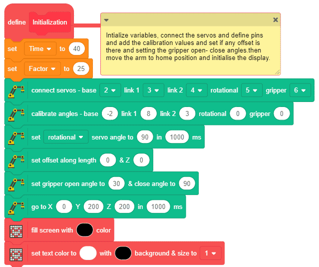
We will also, make a custom block to show the location on the X, Y, and Z axes continuously.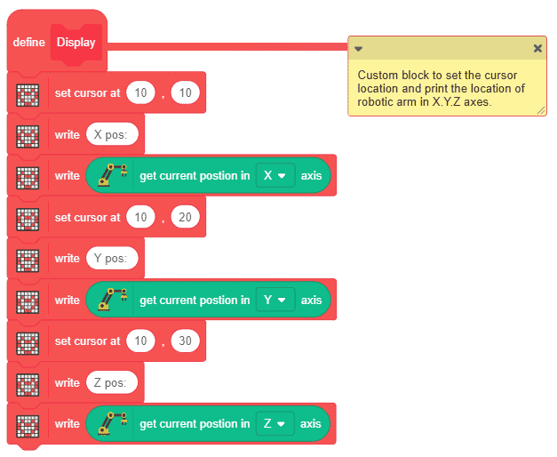
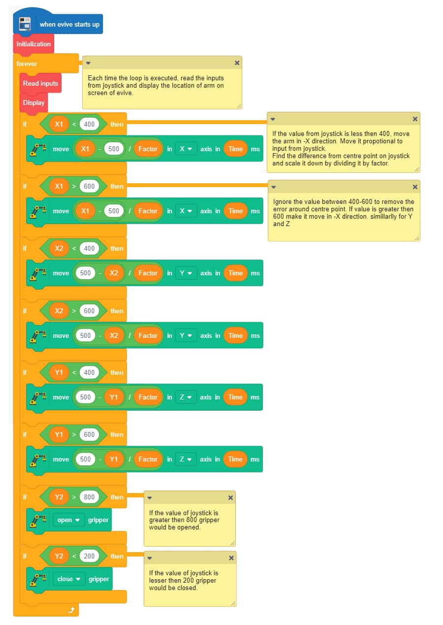
Finally, we need our main script to start executing as soon as evive starts up.
- Firstly, we will initialize the robotic arm. Then we will continuously read the input values of the joysticks and display it continuously on the evive’s screen.
- Now, to check the input values, we will use the if blocks. The joystick is an analog device. So, to control the speed of the arm we must use analog values between 0-1023.
- First, we will check if the value is less then 400. If it is, then move the arm by the value obtained by dividing the difference between the joystick value and the center of the joystick which is 500 by the factor. We are using the division factor to scale down the value. This will make the arm move along the negative X-axis. You can change the values of factor and time to control the response and sensitivity of joysticks to your liking. Add another if block to check if the values are greater then 600 to move the arm along the positive Xaxis.
- Similarly, complete the script for positive X and Z and negative X and Z axes.
- If the value of the right joysticks along the Y-axis is greater then 800 we will open the gripper; if it is less than 200, then we will close the gripper.
Upload the script to evive.
Conclusion
With this, your DIY claw machine is ready. Have fun!


 For Construction Sites by Abhay Maheshwari 2-6 screenshot")


