
Introduction
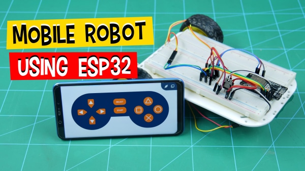
Another day, another robot! Today, we’re going to make yet another smartphone-controlled robot; not using evive but ESP32. In this project, we will first go through the assembly, then the circuitry, it is working, and then finally write the code to program it in PictoBlox – a graphical programming software with advanced interaction capabilities. The robot will go forward, backward, right, and left. We’re going to control it using Dabble, our project interaction, and controller mobile application.
You can download PictoBlox from HERE and get Dabble on Google Play.
Beginning in 3… 2… 1… NOW!
Making of the 2-Wheel Drive
The final assembly will look something like this: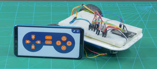
Let’s begin the assembly of the 2-wheel drive robot:
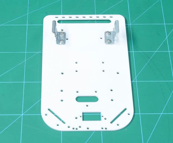
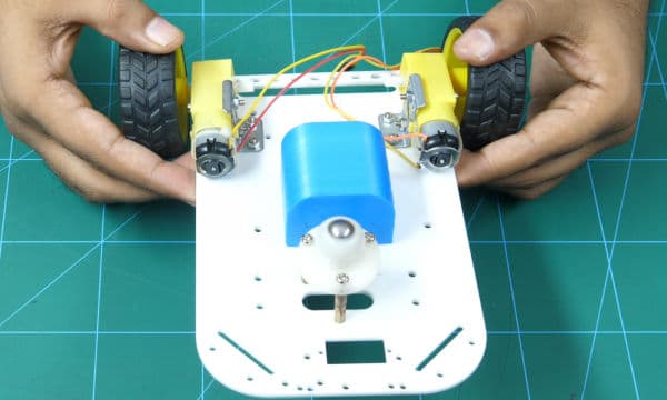
- The following image shows the annotated base of the robot or chassis.
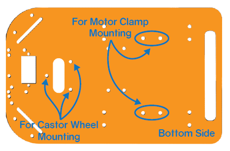
- Take the motor mounting brackets and attach it to the bottom side of the chassis using M3 bolts of 8mm length and M3 nuts.
- Take two Dual Shaft BO motors and attach it to the motor brackets M3 bolts of 25mm length and M3 nuts.
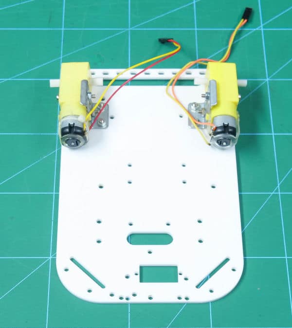
 Make sure that you face the motors in such a way that the wires should face forward and are placed inwards.
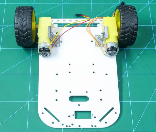
 - Now, fit the wheels into the protruding motor shafts.
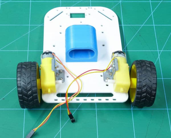
- We need to give an external battery to power up our ESP32. Thus, fasten a 3D printed battery holder at the base of the chassis using M3 nuts and bolts.
- It’s time to attach the third support which is the Caster wheel. Take the Caster and mount three M3 standoffs (20 mm) on it.
- Fasten the standoffs to the chassis using M3 bolts of 8mm length. Fasten the Caster wheel on the standoffs using M3 bolts of 12 mm length.
- Finally, flip the entire assembly.
Connecting the ESP32
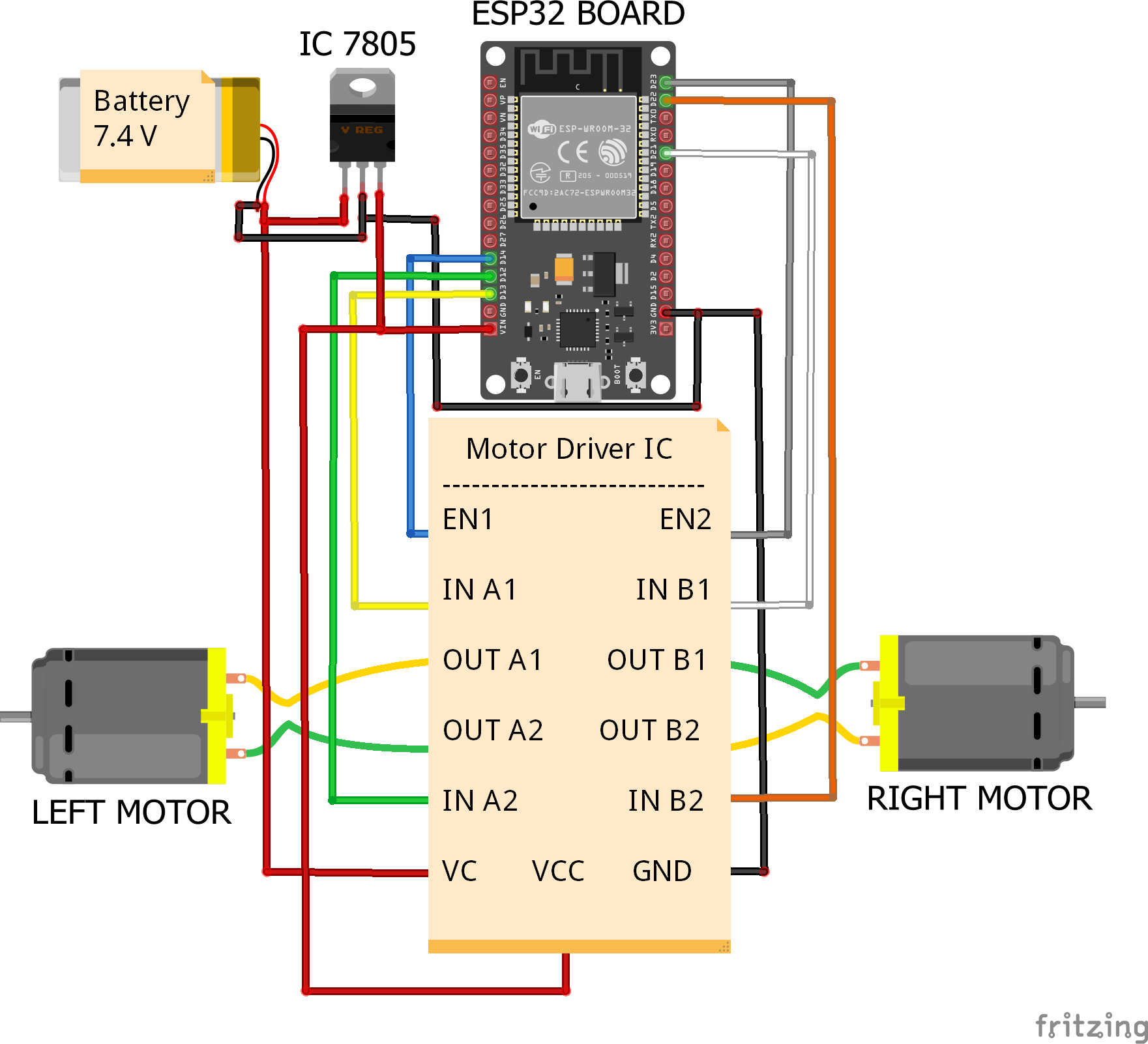
Connect the ESP32 board, Voltage Regulator and Motor Driver on the Breadboard as shown in the below figure: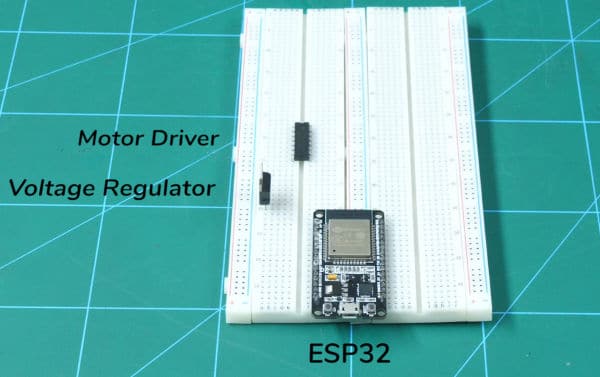
- Connect battery +ve terminal to input of 7805 voltage regulator IC and” VIN” of Motor driver IC
- Connect its -ve terminal to “GND” of ESP32 Dev Board,” GND” of Motor Driver IC, “GND “of the Voltage regulator IC ( 7805)
- Connect OutPut of voltage regulator IC to” VIN” of ESP32 Dev Board and “VCC” of Motor Driver IC
- Connect Motor1 Enable Pin i.e EN1 present on the motor driver IC to pin D14 present on the ESP32 Dev Board. similarly, Connect EN2 to pin D23 of the ESP32 Dev Board
- Connect Motor 1 Direction Control Inputs pin (i.e Pin IN A1 and IN A2) to D12 and D13 pin present on the ESP32 Dev Board respectively.
- Connect Motor 2 Direction Control Input pin (i.e Pin IN B1 and IN B2) to D22 and D23 respectively.
- Connect one end of motor 1 to OUT A1 and another end to OUT A2 .similarly, Connect one end of motor 2 to OUT B1 and another end to OUT B2
Make the connections as shown in the below figure:
Completing the Assembly
Once done with the connections, place the breadboard on your two-wheel robot above the chassis and fix it using a Double-sided tape
Once done, connect a 7.4V Lithium Polymer Battery to ESP32.
Your robot is thus complete.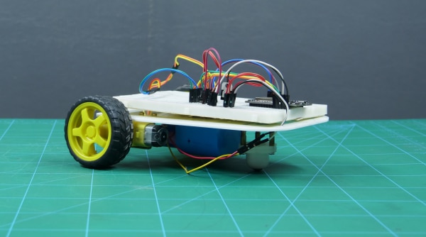
Controlling the Robot
Here, we are communicating wirelessly by our Smartphone which can be done using Dabble. We will give the instructions to the robot by pressing the buttons on the gamepad in the Gamepad module in Dabble.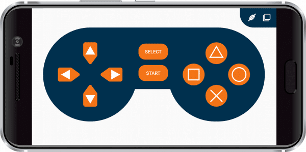
The robot takes actions according to the button pressed. For example,
- Up: Robot will move forward
- Down: Robot will move backward
- Left: Robot will turn left
- Right: Robot will turn right
- If none of the buttons is pressed, the robot will stop.
Coding the Robot
To make the controlling of the ESP32 robot even easier, we are going to write it’s code in PictoBlox: a graphical programming software.
Simply, drag and drop the following stack of code, upload it to ESP32 and make it dance to your tune.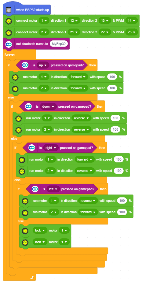
Conclusion
With this, your robot is now ready! Have fun!