
Introduction
Everything these days is becoming smart. Our phones are smart, our cars are smart; so, why not our homes! Time to change the way you control the lights and fans of your home with this project on Home Automation. All you need is evive, some wires, loads of DIYing, your Smartphone, and the Terminal module of Dabble – a project-making mobile application with multitudinous features! You can get the app here.
Ready to take the light control to the next level? Hop on board!
Relays
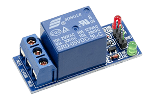
A relay is a switch that is operated through an electrical signal. They are mainly used in controlling high power circuit with a low power signal. For example, with the help of a relay, you can control an AC bulb with evive.
Working of a Relay
A relay consists of an electromagnetic coil and a Single pole double throw switch (SPDT). An SPDT switch has one input and two outputs. As seen in the image there is a part in the symbol with marking NO, NC, and COM on it, that is an SPDT switch.
In this COM is the input of the switch, NC means normally closed and NO means normally open. Both NC and NO are outputs of SPDT switch. The contact that connects the output to input in SPDT is called pole. The spring-like structure symbolizes an electromagnetic coil.
When the coil is not energized NC and COM remains connected in SPDT. As soon as the coil is energized NO and COM gets connected. Actually, when the coil is energized magnetic field is generated around it, the pole gets attracted towards this field and it shifts itself from NC to NO. Hence NO and COM gets connected. As soon as coil gets de-energized coil losses its magnetic field and pole moves back to original position and NC and COM gets connected again.
If you want to know more about relays, visit this tutorial: https://thestempedia.com/tutorials/interfacing-relay-evive/
Circuit Diagram
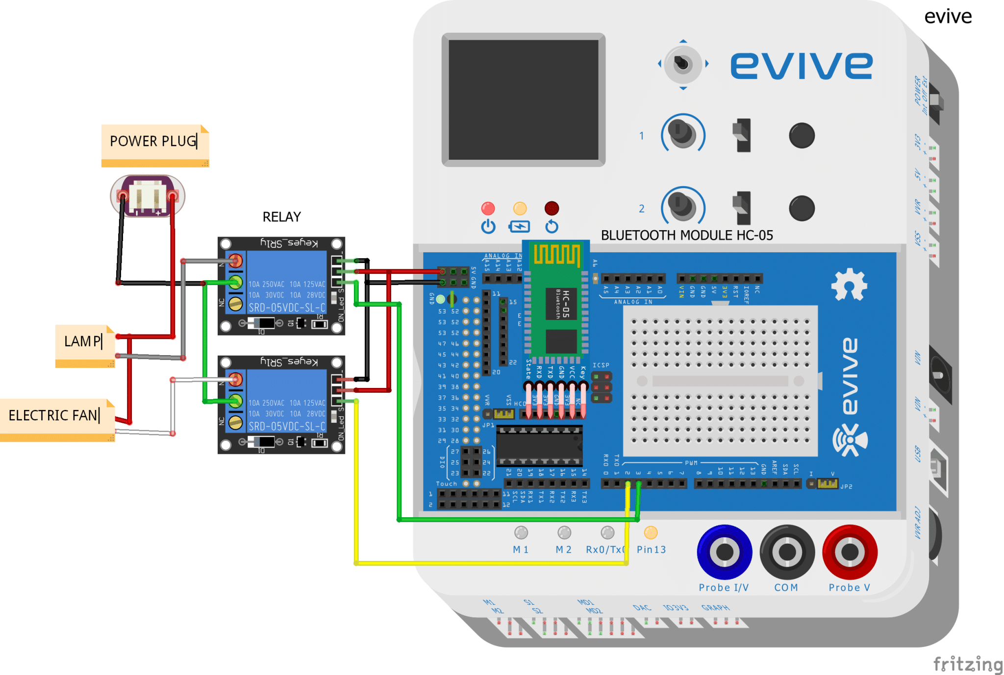
In this project, we will show you how to control an AC light and a fan. You can expand the number for devices you want to control by using more relays.
- Connect the HC-05 Bluetooth Module to the Bluetooth header on evive.
- Connect the COM(Common) terminal of each relay to the ends of each device i.e. to the ends of lamp and fan.
- Connect the NO(Normally Open) terminals of the relays to the other ends of the devices.
- Connections of the relays with evive:
- VCC – VCC of evive
- GND – GND of evive
- INPUT(lamp) – Digital Pin3 of evive
- INPUT(fan) – Digital Pin2 of evive

Dabble – Terminal Module
The terminal module allows you to both send data to the hardware device and receive data from the hardware device.
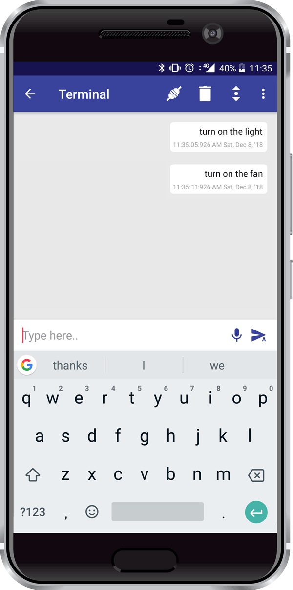
You can send both textual and voice commands to the device e.g. turning it ON or OFF.
We will use Terminal module to control light and fan by sending predefined messages to evive.
Logic
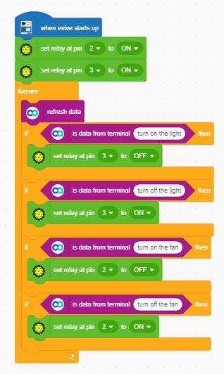
When we give the command turn on the light to the Terminal module of Dabble, it sends this string to evive. Once evive receives the command string, it performs the action corresponding to the string which is written in the code.
The relay is used to switch on/off the lamp/fan.
- turn on the light/ turn on the fan – evive sends a low pulse to the relay
- turn off the light/ turn off the fan – evive sends a high pulse to the relay
- When the pulse is low – relay switches ON the device
- When the pulse is high – relay switches OFF the device
PictoBlox Program
We will make the code in PictoBlox. Follow the instructions.
- Open PictoBlox.
- Select the board as evive:
- Connect the evive.
- Add Dabble Extension by clicking on add extension on the bottom left corner.
- Create the following script using when evive starts up the block:
- Upload the code onto evive:
- Open Dabble App and connect the Bluetooth.
- Open terminal module and start sending the commands.
Conclusion
With this, you are all set to automate your home using your Smartphone!
Just wanted to tell you that we’re only a week away from the launch and are super duper excited for it! To more about it and get exclusive perks, visit here!


 1-18 screenshot")


 I Aradhya Gupta I 7th I DL DAV Model School SB I CODEVOUR 2022 2-16 screenshot")


