
Introduction
You’re comfortably sitting on your bed with your laptop in front playing your favorite movie. The movie has just reached the best scene when you cannot tolerate the cold any longer. Not again! You’ll have to now pause the movie right there, get up, and go all the way to the switchboard across the room just to turn that one switch OFF! But wait! What if we told you that you could control the lights and fans of your room, sitting in one place, with just a few taps on your Smartphone?
Behold the IoT Based Home Automation System! Using its powers you can easily turn OFF the fan whenever you like and then turn it back ON without even moving an inch. Priorities = Sorted!
Hop right in if you want to develop such a system for yourself too!
Assembly
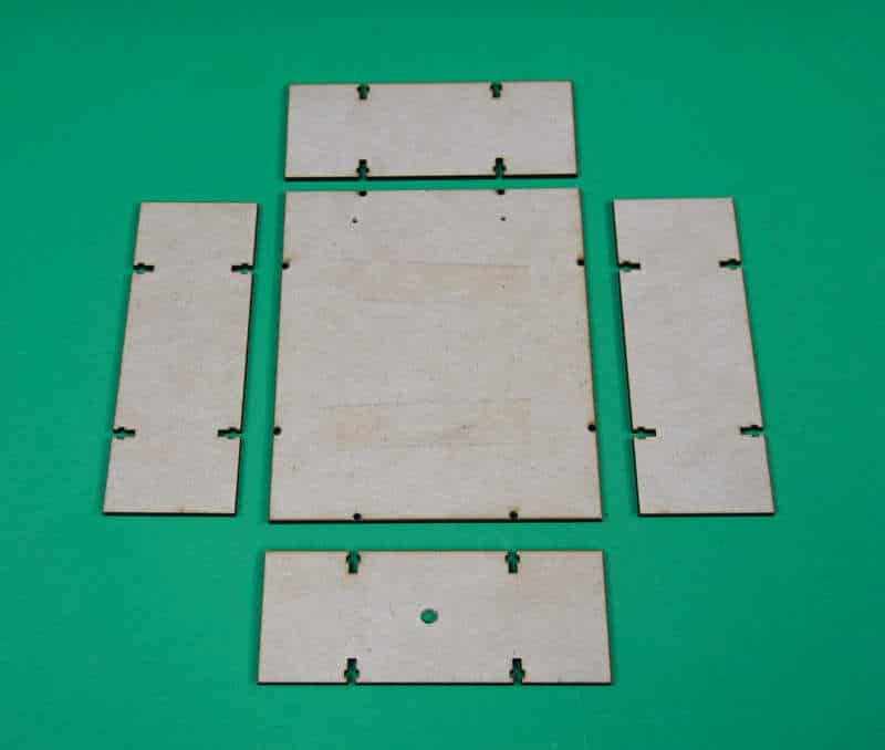
The first thing we need to start assembling is the box, this will be holding the evive.
- Assemble the box using the M3 bolts and nuts.
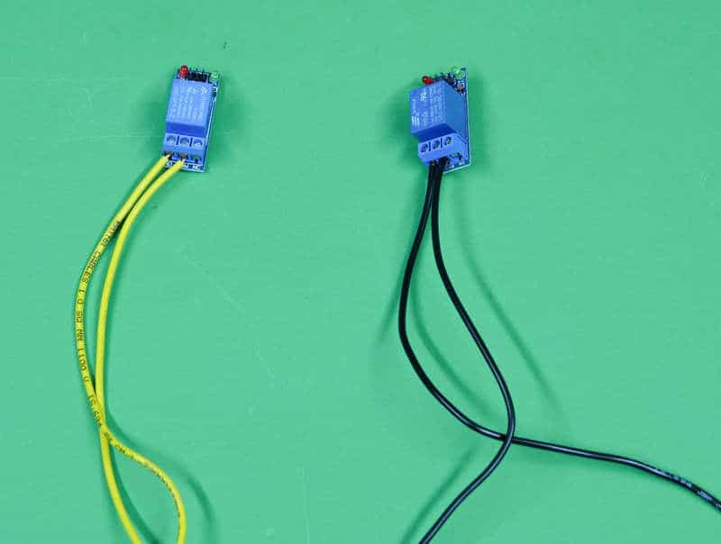
- Now its bring it the relay. Cut the electric wires using the wire cutter and insert them into the relays.
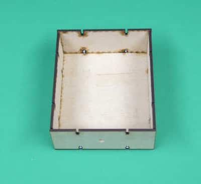
- Then, glue evive and relays into the box.
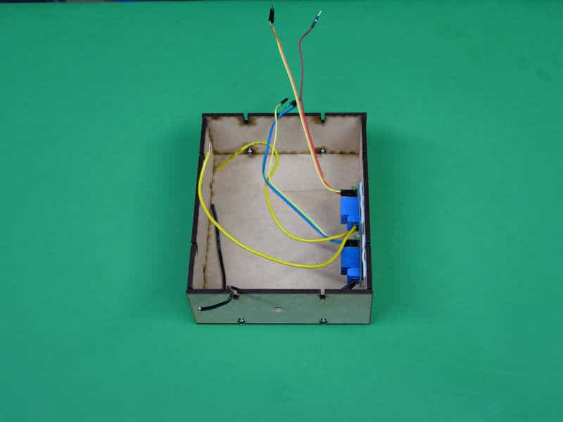
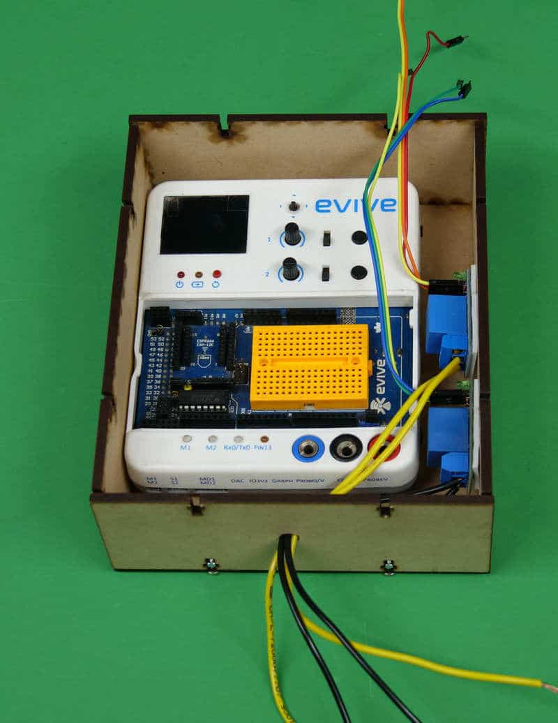
- We have used two relays as we are going to control two switches, Fan and Tubelight.
- Now, pass these wires through the hole at the bottom of the box.
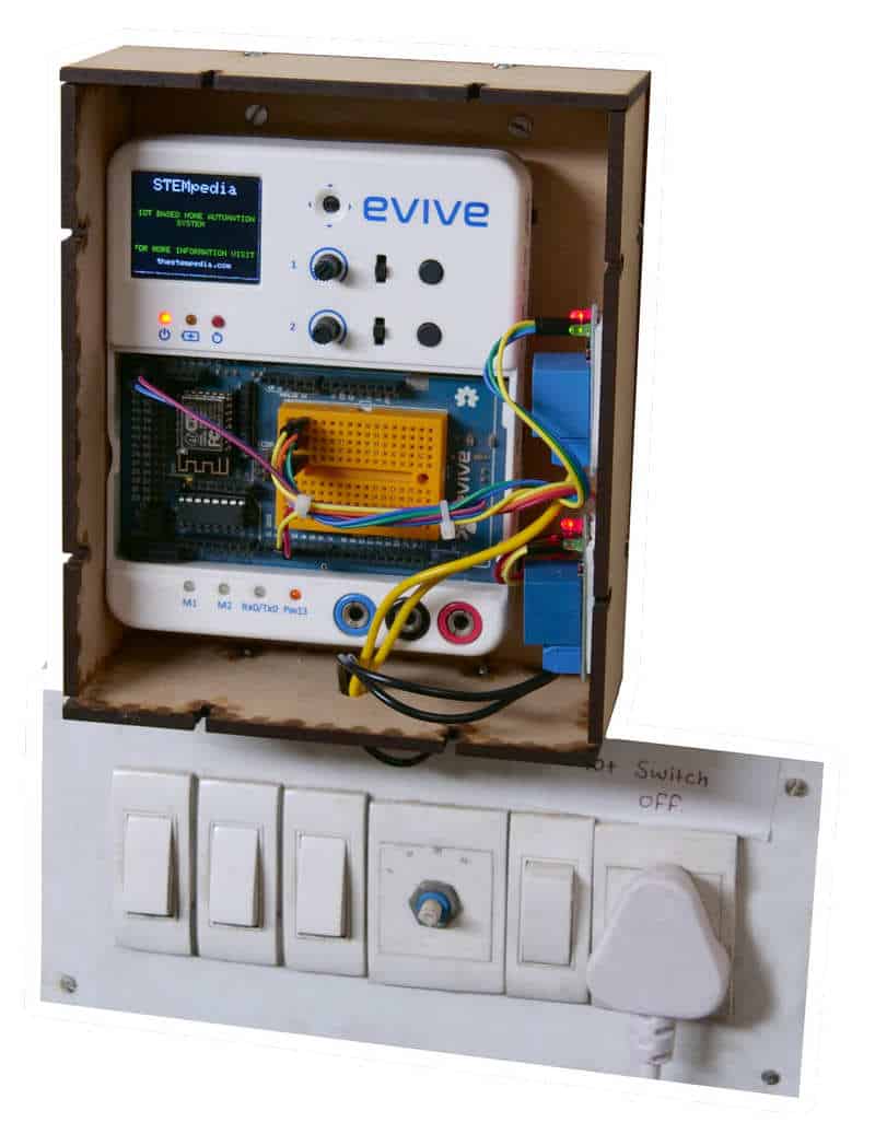
- It’s time to connect the wires to the switchboard of your house.
- Open up the switchboard and place the evive box near the switchboard.
- Now to the two terminals of the switches connect the relay wires.
- Close the switchboard and you are done!
What is Home Automation?
Home Automation is what makes us call our place a Smart Home. We can control all the appliances at our home using a mobile or a laptop. The devices within the home automation system connect with each over a local network. When connected with the Internet, home devices are an important constituent of the Internet of Things.
Mainly Home automation is to control or monitor signals from different appliances. Simply, this helps to make our lives easy.
Logic
We are going to WiFi Module ESP8266 so that we can operate the switches even when we are far from home.
We have programmed our WiFi Module so that it acts as a server.
It will generate an IP Address with which we will be able to connect to the system. You can find the IP Address by connecting to the Serial Monitor of Arduino.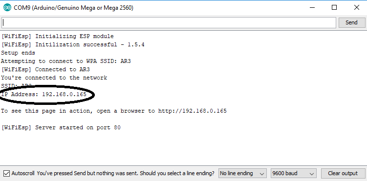 Once we send the HTTP request to the server, the server process the request. Once the server process the request, the corresponding action will be performed and in response, the page will be updated.
For E.g., if the light is OFF and you request to turn it ON. The relay will be triggered and the switch will turn ON.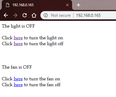
This will switch ON the light and will update the page.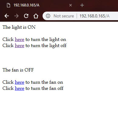
Circuit Diagram
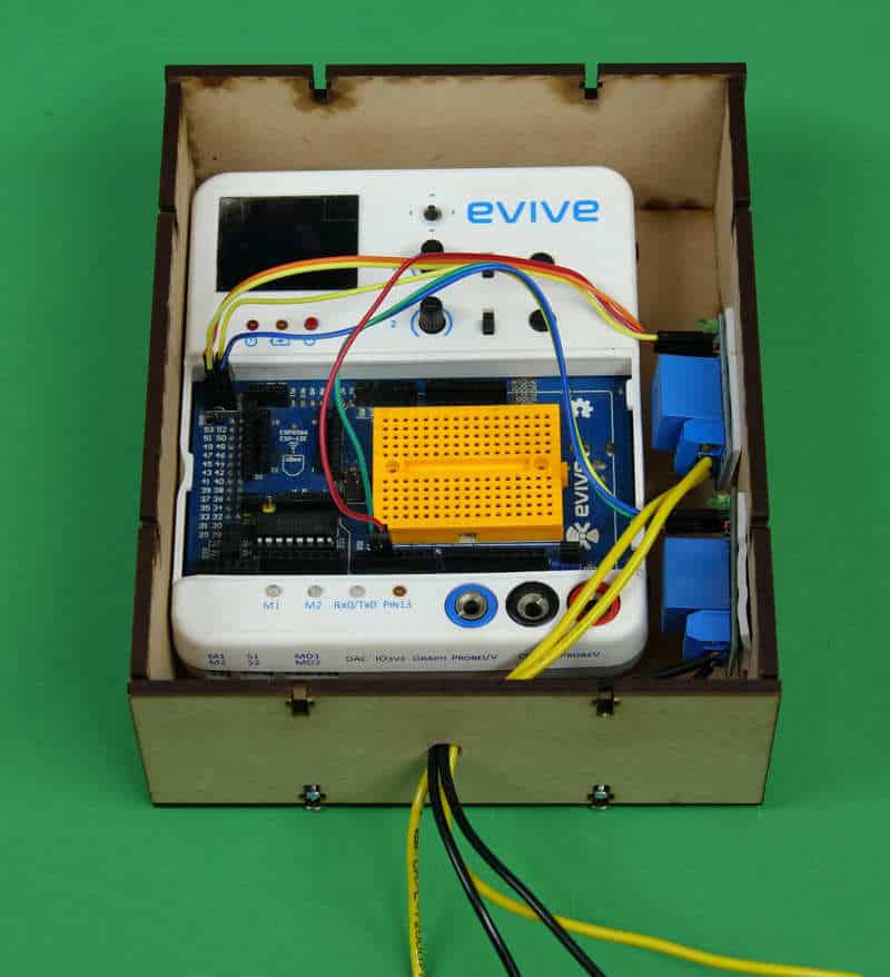
Connections are given as below:
- VCC – +5V on evive
- GND – GND on evive
- SIGNAL – Digital Pin 2 and 3
Connect the Normally Open and COM to the two terminals of the switch.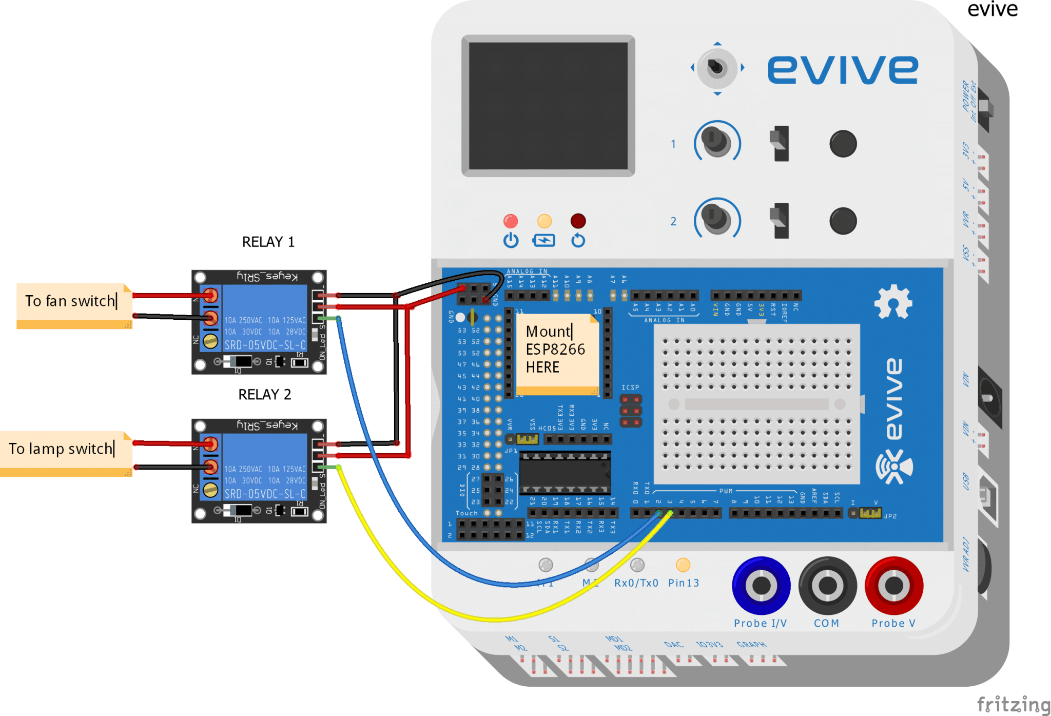
Code
The following code shows how to code for home automation:
Conclusion
With this, your DIY IoT based Home Automation System is ready! Nothing can stop you now from enjoying the movie. Go, my friend, live your life to the fullest!


