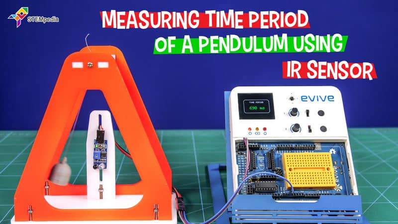

Introduction
Calculating on paper is never an easy job. And when it comes to formulas with sub-formulas of their own, it is nothing short of a nightmare! Take the case of a simple pendulum, which has a variable with a formula of its own.
What if there was a way to replace these scary calculations with a simple computer program?
You guessed it right! With the help of evive, an IR sensor, a computer program, and little DIYing, you can easily find out the time period of the pendulum in a matter of seconds!
So, what are you waiting for? Let’s get into it right away!
Assembly
- Cut out the cardboard according to the dimensions given below:
A = 160 mm x 85 mm
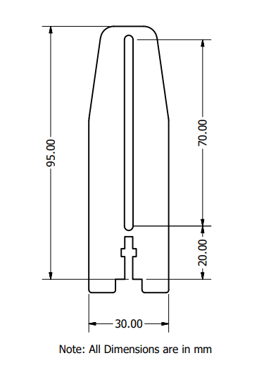
B = 30 mm x 95 mm
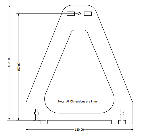
C = 150 mm x 162 mm
D = 150 mm x 162 mm
E = 75 mm x 34 mm
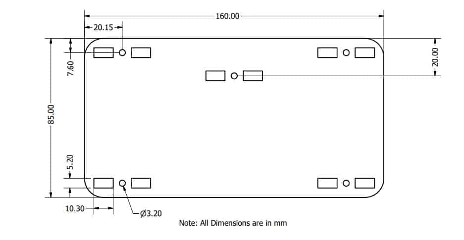
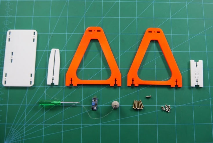
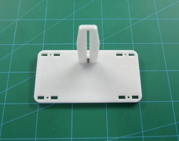
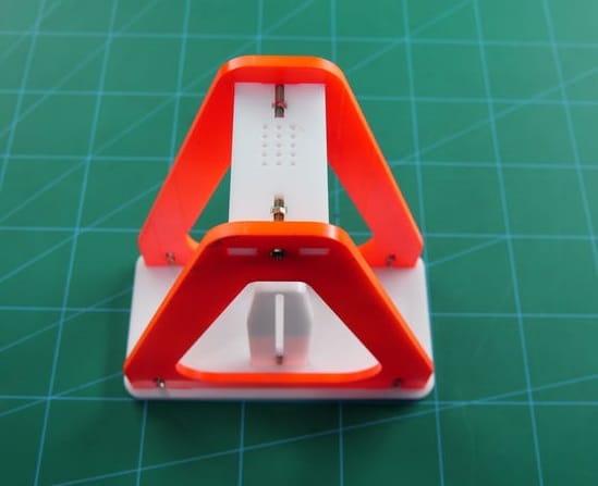
- Take the base piece i.e, piece A.
- Now, take the smaller piece B which holds your sensor and attach it to the base plate using M3 bolts of 20 mm and M3 nuts.
- Take piece C and attach it to the base using M3 bolts of 20 mm and M3 nuts.
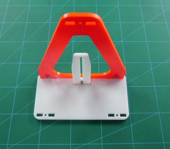
- Similarly, take the other piece i.e D and fix it using M3 nuts and bolts to the base.
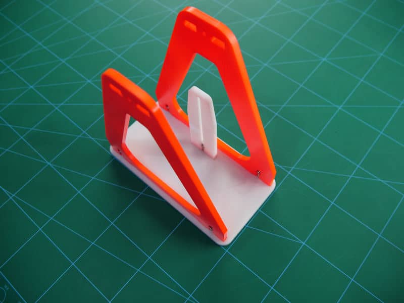
- Now, take the last Acrylic piece i.e E and attach it between the gaps of the piece C and D using M3 nuts and bolts. On this plate, we will be attaching the bob of the pendulum.
The base assembly is ready. All we need to attach is the Sensor and the bob which is a small weight attached to the string at its end. - We will start fixing the sensor on plate B in the vertical gap using M3 bolts of 8mm length and M3 nuts.
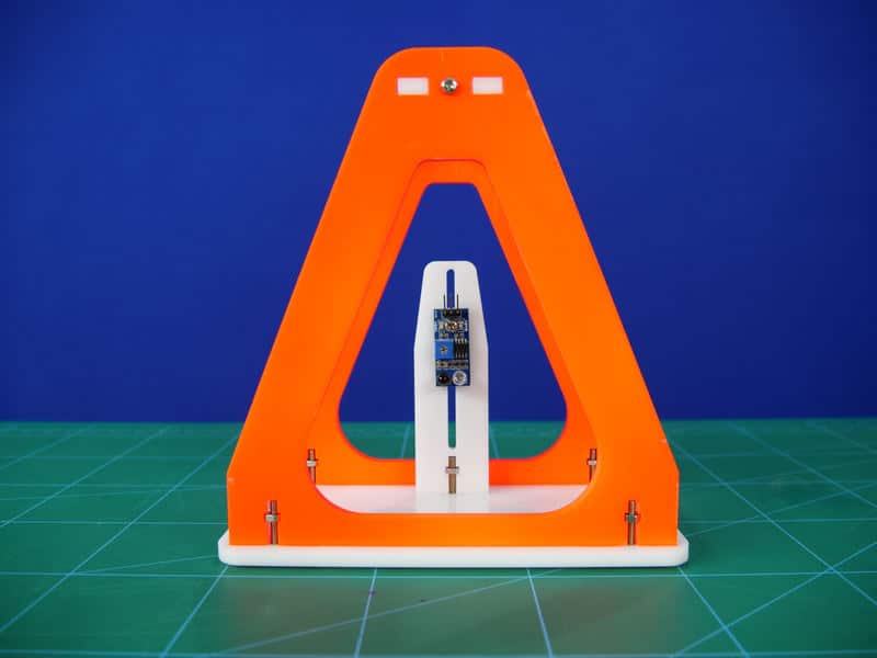
- Once it is attached, it’s time for the last part of the assembly, the bob.
- Bob is nothing but a small weight attached to the string at its end. The bob we used here is a 3D printed one. You can make it using any heavy material or even clay.
- Now, the free end of the string is passed through the hole on the piece E and its length is thus adjusted according to the height required.
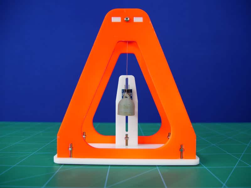
Make sure that the pendulum always remains in the same line as that of the sensor’s LEDs.
Now, the assembly of the simple pendulum is thus complete.
Logic
Here, the IR Sensor calculates the how frequently the bob passes in front of it and thus giving us the Time-Period. Time-period changes on changing the length. Thus, here the IR Sensor successfully calculates the time-period no matter what the length is. Thus, reducing the use of pen-paper based calculation.
The formula we used to calculate on paper is:
T = 2 Π √(l / g)
where,
T = Time Period (milliseconds)
l = Length of the pendulum (measured from the centre of the bob to the end of the string) (millimeters)
g = acceleration due to gravity (m/s2)
Let’s take two cases:
- When l = 118mm,
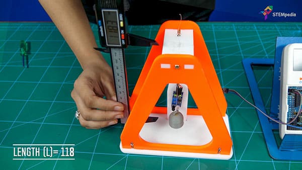
According to the formula: Time-period = 689 milliseconds
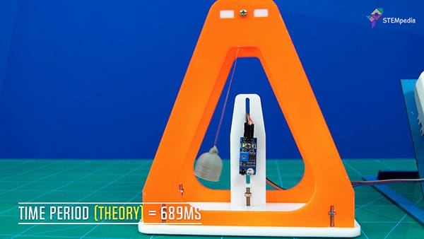
From the activity: Time-period = 689 milliseconds
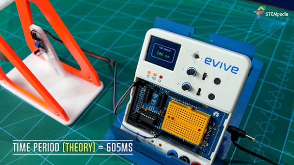
- When l = 91 mm,
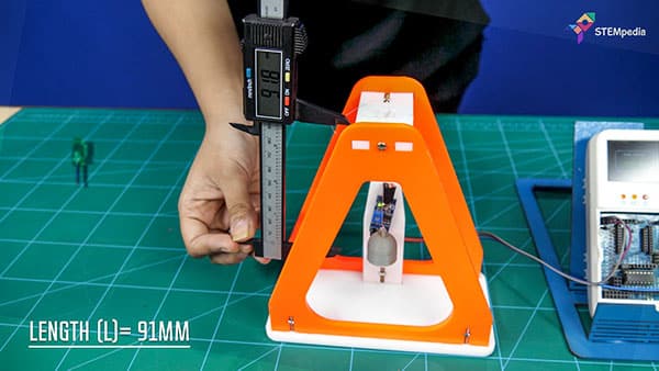
According to the formula: Time-period = 605 milliseconds
From the activity: Time-period = 605 milliseconds
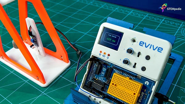
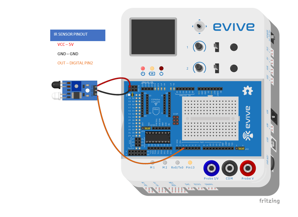
Circuitry
- GND to GND of evive
- VCC to +5V
- OUT to Digital Pin 2
Code
The following code shows how to do the calculations for Time-period:
Conclusion
With this, your setup to calculate the time period is complete! Watch as evive and the sensor perform their magic with the help of the code you wrote!


 For Construction Sites by Abhay Maheshwari 2-6 screenshot")


