Introduction
evive has two bi-directional logic level shifters which are accessible from digital pin 36 and 37 in Arduino IDE and the flow of direction is controlled by digital pin 33. evive use 74LVC245 for level shifting.
Programming in Arduino IDE
- By changing the state of digital pin 33, you can change the characteristics of the logic shifter as an input or output.
- If the state of digital pin 33 is HIGH, then the IO3V3 pins act as OUTPUT pins,
- If the state is LOW, then they act like INPUT pins.
 Note: The digital pin 33 should always be configured as the output.
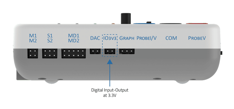
- Digital pins 36 and 37 are directly connected to the level shifter. The level shifter takes 5V input and output from the digital pins and converts them to 3.3V I/O. These 3.3V I/O pins are shown in the figure.
- If you want to give 3.3V output from these pins then you have to configure digital pins 36 and 37 as OUTPUT pins in Arduino IDE.
- You can use IO3V3 pins as input anytime without configuring them as INPUT or OUTPUT.
 Alert: But you have to change the state of digital pin 33 to LOW before reading.
Example
This code demonstrates the use of a bidirectional logic shifter as 3.3V digital output and input. Connect the positive pin of the LED to IO3V3 pin 1 and the negative pin to the GND.
The code will link the LED using 3.3V digital output as well as read the state of the LED and IO3V3 pin 2.
/*
 This code demonstrate the use of bidirectional logic shifter as 3.3V
 digital output and input. Connect the positive pin of the LED to IO3V3
 pin 1 and negative pin to the GND.
 This code will link the LED using 3.3V digital output as well as read the state of LED and IO3V3 pin 2.

 Modified by Pankaj Kumar Verma
 on 18 Jan, 2017
 */

int handlePin = 33;                   // Control pin connected to digital pin 33
int outPin = 36;                      // Output pin connected to digital pin 36
int inPin = 37;                       // Input pin connected to digital pin 37

void setup() {
  pinMode(outPin, OUTPUT);            // Configure digital pin 36 as output
  pinMode(handlePin, OUTPUT);         // Configure digital pin 33 as output
  pinMode(inPin, INPUT);              // Configure digital pin 37 as input

  Serial.begin(9600);                 // Start Serial
  Serial.println("Start");
}

void loop() {
  digitalWrite(handlePin, HIGH);      // Logic shifter work as output
  digitalWrite(outPin, LOW);
  delay(1000);

  digitalWrite(handlePin, LOW);       // Logic shifter work as input
  Serial.println(digitalRead(inPin));
  Serial.println(digitalRead(outPin));

  digitalWrite(handlePin, HIGH);      // Logic shifter work as output
  digitalWrite(outPin, HIGH);
  delay(1000);

  digitalWrite(handlePin, LOW);       // Logic shifter work as input
  Serial.println(digitalRead(inPin));
  Serial.println(digitalRead(outPin));
}
Conclusion
In this lesson, you learned how to use the bi-directional logic level shifter of evive. Depending on the state of digital pin 33, you can use the IO3V3 pins as either output or input. You also learned how to configure the digital pins 36 and 37 as input or output in Arduino IDE, and how to read the state of the output pins using the digitalRead() function. With this knowledge, you can now use the IO3V3 pins of evive for different applications!


