Introduction
A servo motor is a rotary actuator that rotates with angular precision.There are different types of servos available namely: positional rotation, continuous rotation, and linear. Here you will be using positional rotation servo. It is used to achieve proper angular positions for objects connected to it. Servo motors are used widely in projects related to robotics.
If pull apart a servo motor, you find the following inside it:
- A DC Motor
- A Potentiometer
- A gear train, i.e. a series of gears that are connected such that their teeth are engaged/interconnected. (A gear can be visualised as wheel with teeth, not the regular teeth though; sometimes more and sometimes less than 32!)
- A control circuit: This circuit is the actual brain behind the precise working of the servo. It controls how much the servo should move or rotate depending upon the input it receives.
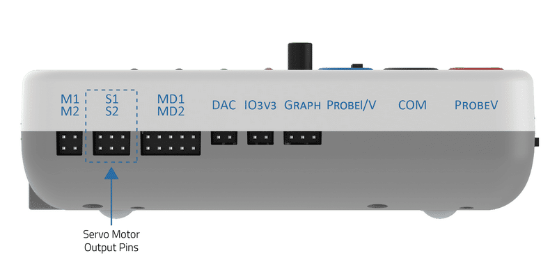
evive has two dedicated servo motor outputs pins, as shown below:
How to control the Servo Angle
A positional servo mainly consists of three pins: GND, Vcc, and Signal pin. Its shaft rotates from 0 to 180 degrees, 0° being its neutral position. The signal pin on servo should be given a pulse every 20ms (milliseconds) to move it to a specific angular degree from its neutral position. The width of the pulse applied decides the amount of angular rotation the servo performs. This pulse is given from the PWM pins of the controller.
The signal pin of servo 1 is connected to digital pin 44 and servo 2 is connected to digital pin 45 in evive. Slots S1 and S2 shown in the above images are for servo 1 and servo 2 respectively.
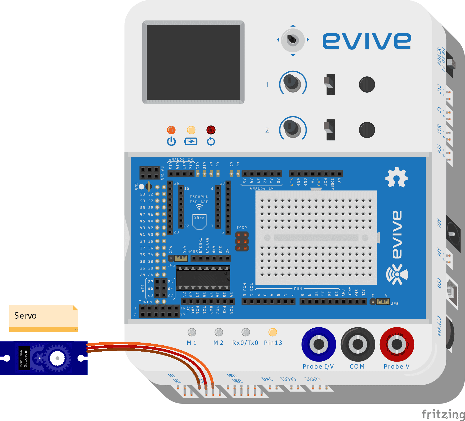
Connecting servo to evive
For interfacing the servo motor with Arduino IDE, you must first connect the motor to one of evive’s servo channels as shown in the figure below:

Example
Example 1: Servo is rotated from 0° to 180° and from 180° to 0°.
/* Sweep


  This example runs servo from 0 to 180 degree and reverse i.e from 180 to 0 degree.
  To control servo 1(S1) use SERVO1_ATTACH.
  To control servo 2(S2) use SERVO2_ATTACH.

  Explore more on : https://thestempedia.com/tutorials/servo/

*/

#include <evive.h>
Servo servo;  // create servo object to control a servo
// twelve servo objects can be created on most boards

int degree = 0;    // variable to store the servo position

void setup() {
  servo.attach(SERVO1_ATTACH);  // attaches the servo on pin S1 to the servo object
}

void loop() {
  for (degree = 0; degree <= 180; degree += 1) { // goes from 0 degrees to 180 degrees
    // in steps of 1 degree
    servo.write(degree);              // tell servo to go to degreeition in variable 'degree'
    delay(15);                       // waits 15ms for the servo to reach the position
  }
  for (degree = 180; degree >= 0; degree -= 1) { // goes from 180 degrees to 0 degrees
    servo.write(degree);              // tell servo to go to degreeition in variable 'degree'
    delay(15);                       // waits 15ms for the servo to reach the position
  }
}
Example 2: You will control the servo motor using evive’s potentiometer.
/*
   evive servo example
   This example demonstrates how to use servo motor on evive.
   For this servo is rotated as per movement of POT1 on evive.
   One can also use POT2 of evive for same purpose.

  To control servo 1(S1) use SERVO1_ATTACH.
  To control servo 2(S2) use SERVO2_ATTACH.

   Explore more on : https://thestempedia.com/tutorials/servo/

*/
#include<evive.h>
Servo myservo;  // create servo object to control a servo
int angle=0;
void setup() {
  myservo.attach(SERVO1_ATTACH);  // attaches the servo on pin S1 to the servo object
}

void loop() {
  angle = analogRead(POT1);            // reads the value of the potentiometer (value between 0 and 1023)
  angle = map(angle, 0, 1023, 0, 180);     // scale it to use it with the servo (value between 0 and 180)
  myservo.write(angle);                  // sets the servo position according to the scaled value
  delay(15);                           // waits for the servo to get there
}
Conclusion
In conclusion, servo motors are useful for projects related to robotics because of their precise angular rotation capabilities. The evive board has two dedicated servo motor outputs pins and can be connected to and controlled by either the Arduino IDE or evive‘s potentiometers. Through this lesson, you have learned how to control the servo motor using the Arduino IDE and evive‘s potentiometers.


