Introduction
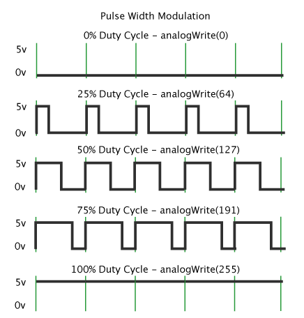
PWM, or Pulse Width Modulation is a technique for getting an analog output using digital signals. A digital signal, in general, can have either of the two values: HIGH/ON or LOW/OFF. If we switch the signal between these two values at an extremely fast rate, say, 500 times in 1 second, the signal at the output will appear to be continuous; it will seem as if it is an analog signal. The duration of on-time, i.e. the time during which the signal is HIGH is called the pulse width. To get varying analog values, you can modulate, i.e. change that pulse width. If you repeat this on-off pattern fast enough, the result is a steady voltage between 0 and 5V.
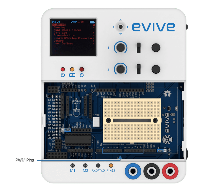
evive generates analog output in PWM form. It has 12 PWM pins for the same; they are numbered 2 – 13. Pin 13 is internally connected to the pin 13 LED.
analogWrite()
Generally, Arduino’s PWM frequency is about 500Hz. In Arduino IDE, we use PWM concept through analogWrite() function. We give a value ranging on a scale of 0 – 255, such that analogWrite(255) requests a 100% duty cycle (always ON), and analogWrite(127) is a 50% duty cycle (ON for one half the time).
Syntax:
analogWrite(pin, value)
where pin is the PWM pin and value is the duty cycle between 0% (always OFF or 0) and 100% (always ON or 255)
Example
In this example we will control the brightness of pin 13 LED with evive’s potentiometer that is internally connected to the analog pin A9. The brightness of an LED depends on the current flowing through it. If we control the voltage supply to the LED, we can control the current flowing though it, and as a result its brightness.

Below is the Arduino sketch:
/*
 This code demonstrate the use of analogWrite(). According to the value
 of the potentiometer 1 of evive, the brightness of the LED is controlled.
 */

int LEDPin = 13; // LED connected to digital pin 13
int PotPin = A9; // Potentiometer connected to analog pin A9
int val; // variable to store the read value\

void setup() {
 // put your setup code here, to run once:
 pinMode(LEDPin, OUTPUT);
}

void loop() {
 // put your main code here, to run repeatedly:
 val = analogRead(PotPin); // Read the value of voltage from potentiometer
 val = val/4;      //this maps the analog reading that vary from 0-1023 to range of 0-255 for using analogWrite function
 analogWrite(LEDPin); // Sets the brightness according to potentiometer state
 delay(50);
}
Conclusion
In this lesson, we learned about Pulse Width Modulation (PWM) and how to use the analogWrite() function to control the brightness of an LED with the help of the evive potentiometer. We also looked at the syntax of the analogWrite() function, and saw an example of how to use it. Finally, we discussed the need for mapping the analog reading that vary from 0-1023 to a range of 0-255 for using analogWrite().


