Introduction
As stated in the previous tutorial a digital input pin can be in either of the three states namely HIGH, LOW or Floating.
- 0V – 1.5V: LOW
- 3.3V – 5V: HIGH
- 1.5V – 3.3V: floating (can either be HIGH or LOW)
In this tutorial, you will be using digital pin 38 of evive as an input since it is connected to tactile switch 1 on evive. You will read the state of digital pin 38 to check when tactile switch is pressed and depending upon the state of the tactile switch a bar of particular color will be printed on evive screen.
Configuring a Digital Pin as an Input Pin
In evive digital I/O pins are by default set as input pins and hence they don’t need to be explicitly declared as INPUT initially in the program. But it is advised to declare each and every pin as input or output for consistency.
Digital Input pins can be configured as INPUT by using the following statement:
pinMode(pin, INTPUT);
where the pin is the digital pin number you want to initialize as input.
It is often useful to set an input pin to a known state if no external input is present. This can be done by adding a pull-up resistor (connected to +5V), or a pull-down resistor (connected to ground) on the input. A 10KΩ resistor is both a good pull-up and pull-down resistor.
digitalRead(Pin) is used for reading digital input in Arduino IDE. It returns 1 if it reads HIGH and 0 when it reads LOW.
Example: Displaying the pin state using evive’s Tactile Switch
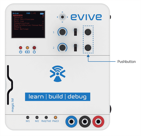
evive has two tactile switches connected to digital pin 38 and digital pin 39. When pressed, the state of the digital pin is HIGH; otherwise, it is LOW. In this Arduino IDE sketch, we will read the state of digital pin 38, which is connected to tactile switch 1, and then display it on the TFT Screen.
Below is the sketch:
/*
evive Digital Read TFT Display

This code demonstrates how to display digital state on TFT Screen
by reding input from TACTILESW1.

TACTILESW1 is a connected to digital pin 38 on evive.

Explore more on: https://thestempedia.com/tutorials/evive-digital-input-2/
*/
#include <evive.h>
boolean state = 0;

void setup() {
Serial.begin(9600);
tft_init(INITR_GREENTAB); // initialize a ST7735S chip, green tab
tft.setRotation(1);
Serial.println("Initialized");
tft.fillScreen(ST7735_BLACK);
pinMode(TACTILESW1, INPUT);
}

void loop() {
tft.drawRoundRect(20, 30, 120, 68, 10, ST7735_WHITE);
tft.setTextColor(ST7735_WHITE);
tft.setTextSize(2);
tft.setCursor(50, 40);
tft.println("STATE");
state = digitalRead(TACTILESW1);    // TACTILESW1 is keyword of digital pin 38 on evive. Here input at this pin is being read.
if (state == 1) {
tft.fillRoundRect(40, 65, 80, 25, 5, ST7735_GREEN);
}
else {
tft.fillRoundRect(40, 65, 80, 25, 5, ST7735_RED);
}
delay(100);
}
Conclusion
In this tutorial, you have learned how to configure digital I/O pins as input, how to read digital inputs using digitalRead(), and how to display the same on evive’s TFT screen. You have also seen an example of how to monitor the state of tactile switch 1, which is connected to digital pin 38 of evive, and display it on the TFT screen.


