Introduction
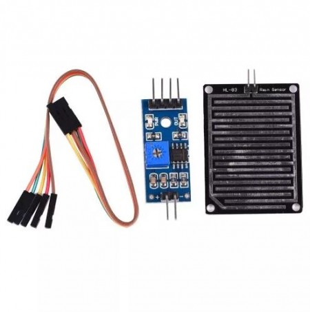
A Raindrop sensor is a board on which nickel is coated in the form of lines. It consists of a detector board and a control board that controls the sensitivity through a potentiometer. The rain sensor detects water that completes the circuits on its sensor boards’ printed leads. The sensor board acts as a variable resistor that will change from 100k ohms when wet to 2M ohms when dry. In short, the wetter the board the more current that will be conducted.
How does the Raindrop sensor work?
It works on the principle of resistance. When there is no water drop on board its resistance is high so we get high voltage. When the water drop is present, it reduces the resistance because water is the conductor of electricity, and the presence of water connects nickel lines in parallel so reducing resistance and as a result, there is reduced voltage drop across it.
Interfacing Raindrop sensor with evive
Wiring
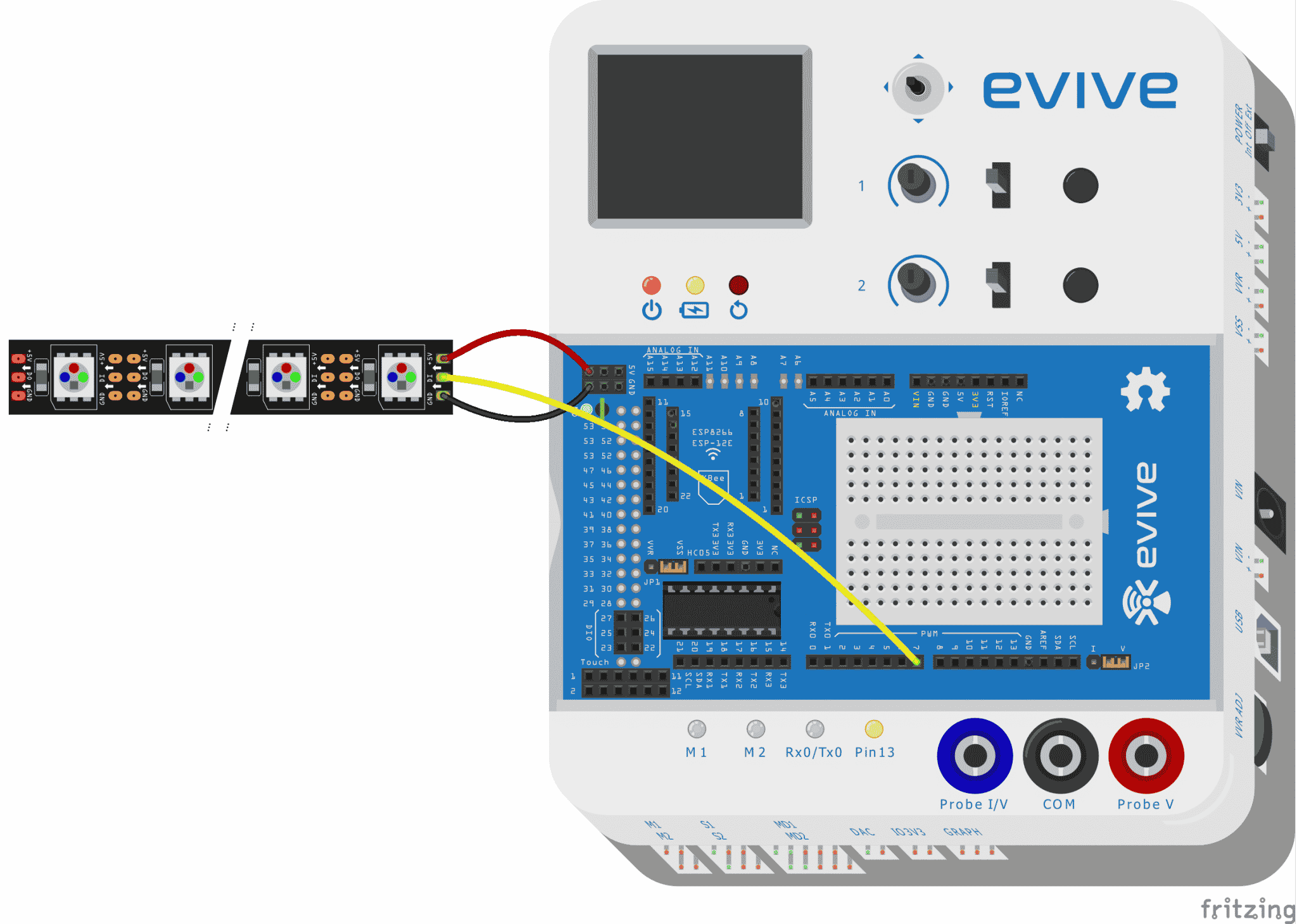
The following circuit diagram explains the circuit connection of the raindrop sensor with evive.

Follow the steps below to connect the sensor to evive:
- First of all, take the detector board and insert two female to female(yellow and green in circuit diagram) wire in the pin slot of the board.
- After this, connect the other end to the control board. From the other end of the control board, connect three female-to-male jumper wires(orange, red, and black in the circuit diagram).
- connections to the evive board:
- GND pin on the control board connects to the GROUND pin on board.
- VCC pin on the control board connects to the 5V pin on board.
- AO (analog output) pin on the control board connects to A0 pin on board.
Controlling RGB strip using Raindrop sensor
Interfacing RGB strip with evive
Follow the steps below to connect the RGB strip to evive:
- First of all, take an RGB strip and solder three male jumpers on each pin.
- connect the +5v jumper to the 5v power supply and the GND jumper to the ground pin.
- connect Din jumper to digital pin no. 7 on board as shown in the circuit diagram.

Arduino Code
After making the complete circuit upload the following Arduino code
- Raindrop sensor Arduino code:
/******************************************************************************* * * DESCRIPTION:This code read the analog as well as digital data from the * raindrop sensorpin and print the data on the serial monitor. * * AUTHOR:Chetan Vashishtha * * DATE:2018/05/23 * * *******************************************************************************/ void setup() { Serial.begin (9600);//initialising the serial monitor. pinMode (2 , INPUT);//initialising pin for the digital communication. } void loop() { int value = analogRead(A0);//variable value stores the analog data from the sensor //uncomment the next line if you want to get the digtal output from the raindrop sensor // //int digital = digitalRead(2); Serial.println (value); //uncomment the next line while using digital pin. //Serial.println (digital); delay(1000); } - Raindrop sensor with RGB strip Arduino code:
/********************************************************************
 *
 * DESCRIPTION:This code demontrates the interfacing of Rain drop
 * sensor and RGB  stip with evive.Raindrop sensor gives the analog
 * value and the RGB  strip glow corresponding to the raindrop sensor
 * value.
 *
 * AUTHOR:Chetan Vashishtha
 *
 * DATE:25/05/2018
 *
 *
*********************************************************************/
#include <Adafruit_NeoPixel.h>
#include <evive.h>
#ifdef __AVR__
  #include <avr/power.h>
#endif

// Which pin on the Arduino is connected to the NeoPixels?
// On a Trinket or Gemma we suggest changing this to 1
int PIN=2;

// How many NeoPixels are attached to the Arduino?
#define NUMPIXELS      7

// When we setup the NeoPixel library, we tell it how many pixels, and which pin to use to send signals.
// Note that for older NeoPixel strips you might need to change the third parameter--see the strandtest
// example for more information on possible values.
Adafruit_NeoPixel pixels = Adafruit_NeoPixel(NUMPIXELS, PIN, NEO_RGB + NEO_KHZ800);

#include<evive.h>
int sensorPin = A0; // select the input pin for the raindrop
int sensorValue = 0; // variable to store the value coming from the sensor
int counter=0;
int delayval = 500; // delay for half a second

void setup() {
  // This is for Trinket 5V 16MHz, you can remove these three lines if you are not using a Trinket
#if defined (__AVR_ATtiny85__)
  if (F_CPU == 16000000) clock_prescale_set(clock_div_1);
#endif
  // End of trinket special code
  Serial.begin(9600);
  pixels.begin(); // This initializes the NeoPixel library.
}

void loop() {

  // For a set of NeoPixels the first NeoPixel is 0, second is 1, all the way up to the count of pixels minus one.
    // pixels.Color takes RGB values, from 0,0,0 up to 255,255,255
    int val=analogRead(sensorPin);
    Serial.println(val);
    for(int j=0;j<7;j++)
    {
      pixels.setPixelColor(j, pixels.Color(0,0,0));
      pixels.show();
    }
    if(val>800)
    {
      for(int i=0;i<3;i++)
      {
        pixels.setPixelColor(i, pixels.Color(0,255,0));
        pixels.show();

      }
    }

    else if(val>500 && val<800)
    {
      for(int i=0;i<5;i++)
      {
        pixels.setPixelColor(i, pixels.Color(255,0,0));
        pixels.show();
      }
    }
    else
    {
      for(int i=0;i<7;i++)
      {
        pixels.setPixelColor(i, pixels.Color(0,0,255));
        pixels.show();
      }
    }
}
Output
The final setup after the connection is shown in the figure.
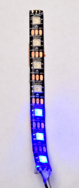
The RGB strip after different variations in the amount of rainfall is shown below.
- When the rainfall is very HIGH.
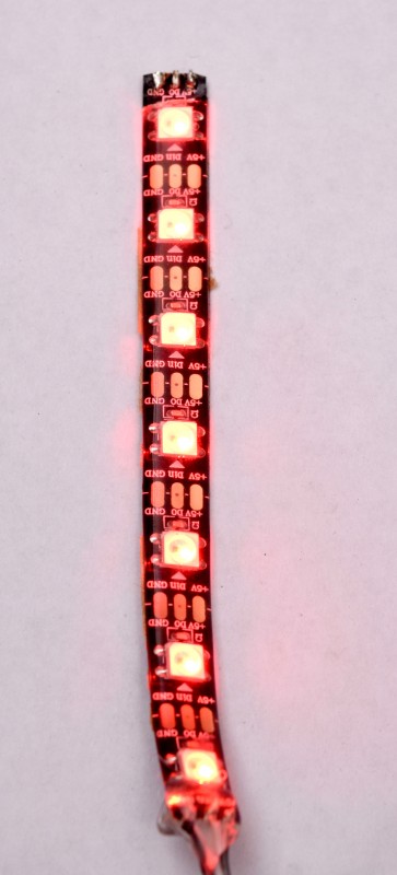
- When the rainfall is MODERATE.
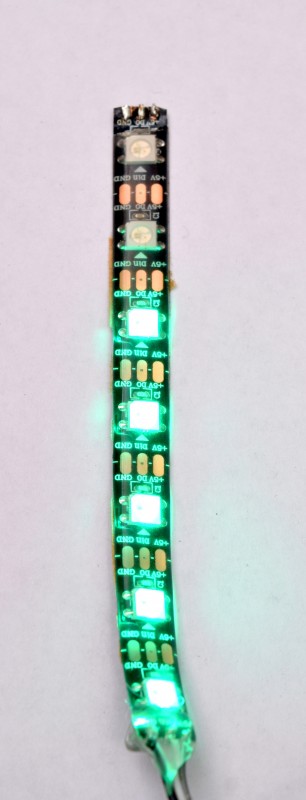
- When the rainfall is LOW.
Conclusion
In this lesson, we have successfully demonstrated how to interface a raindrop sensor with evive and control an RGB strip accordingly. We used a raindrop sensor and interfaced it to evive and discussed the working principle of the sensor. We have also uploaded the Arduino code for the sensor and RGB strip. The RGB strip changes its color depending on the amount of rainfall. This setup can be used to get automated alerts when the rainfall is above a certain level.


