Introduction
In this tutorial, we will be making a digital clock using the “TM1637” 4-digit display and the “RTC PCF8563” real-time clock module. First, we will get “Hour” and “Minute” from real-time clock module and then we will use these hours and minutes to display timing on TM1637 4-digital display.
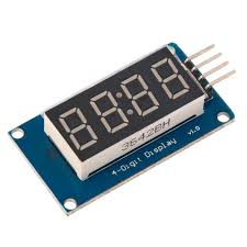
TM1637 4-digit Display
TM1637 is used to drive seven segments display, there are many modules available that countain TM1637 chip to form a 4-digit numerical display module.
Features
- Use either the raw segment value or decimal number
- Set either the whole display or any digit independently
- Control the brightness
- Pure software implementation
Pin Description
TM1637 4-digit display has 4 pins
- VCC
- GND
- CLK (clock pin for I2C communication )
- DIO ( Data Input output pin )
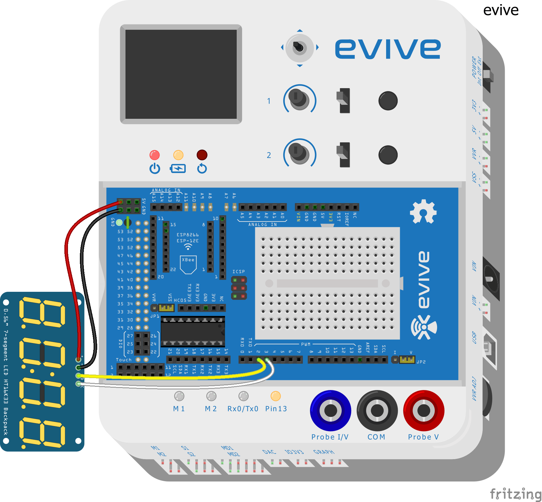
Circuit Diagram
- Connect ‘VCC’ of ‘TM1637’ module to ‘VCC’ of evive
- Connect ‘GND’ of ‘TM1637’ module to ‘GND’ of evive
- Connect ‘CLK’ of ‘TM1637’ module to pin number 2 of evive( Yellow wire in circuit diagram given below)
- Connect ‘DIO’ of ‘TM1637’ modue to pin number 3 of evive(White wire in circuit diagram given below)
Steps for Setting Time
- First connect evive to the computer ( using USB A -B cable ), then upload the code which is given below.
- Then move slid switch-1 to the “UP” position and use Potentiometer-1 and Potentiometer-2 to set the Hour and minute as shown above.
- Potentiometer-1 and Potentiometer-2 are connected internally to analog pins A9 and A10 of evive respectively, they will give digital readings (from 0 to 1023), and we will use the map function to convert them (from 0 to 59 and 0 to 12) for minutes and hour.
- After setting the time using potentiometer-1 and potentiometer-2, move slid switch-1 to the “Down” position, this will start to display timing on the TM1637 4-digit display module.
Arduino Code
/*
 *  evive
 *  this tutorial demonstarte digital clock using TM1637 display and RTC PCF8563
 *
 *  25 may 2018
 *  by punit chotaliya
 */
#include <Wire.h>
#include <Rtc_Pcf8563.h>
#include <TM1637Display.h>

#define CLK 2             // connect ClK to pin number 2
#define DIO 3            // connect DIO to pin number 3

//initialized the real time clock
Rtc_Pcf8563 rtc;

TM1637Display display(CLK, DIO);             // creating object named as display

int time_set_sw = 40;                      // when slid switch-1 is in "up" position it is connected to pin number 40
int hour_val = 0, minute_val = 0;         // declaring variable for storing hour and minute value
int hour_pot = A9;                       //Potentiometer-1 is connected to A9
int minute_pot = A10;                   //Potentiometer-2 is connected to A10

uint8_t clear_segment[] = {         //  declaring array for clearing
  0x00, 0x00, 0x00, 0x00  };       //display

void Set_Time()                         //This function  is used to set time with help of slide switch and potentiometers.
{
  set_Brightness(40);                 // this functon set brightness
  while (digitalRead(time_set_sw))   // while slid switch is in "up" position execute while loop
  {

    hour_val = map(analogRead(hour_pot), 0, 1023, 0, 23);                           // to map analog values read to hours
    minute_val = map(analogRead(minute_pot), 0, 1023, 0, 59);                      // to map analog values read to minutes
    display.showNumberDecEx((hour_val * 100) + minute_val, 0x80 >> 1, 1, 4, 0);   // dispaying value of hour and minutes on display
    /*Serial.print(hour_val);
      Serial.print(":");
      Serial.println(minute_val);*/
  }

  rtc.setTime(hour_val, minute_val, 0);
 //Blinks Time once it is set through above steps.
  clearSegment();
  delay(50);

  display.showNumberDecEx((hour_val * 100) + minute_val, 0x80 >> 1, 1, 4, 0); //
  delay(50);

  clearSegment();
  delay(50);

  display.showNumberDecEx((hour_val * 100) + minute_val, 0x80 >> 1, 1, 4, 0);
}


void clearSegment()          //To clear all segments of display
{
  display.setSegments(clear_segment);
}


void set_Brightness(int value)      // Enter any value from 0-100 for varying brigthness of display from 0% to 100%
{
  display.setBrightness(map(value, 0, 100, 0, 7));
}

void setup()
{
  //Serial.begin(9600);
  clearSegment();
}

void loop()
{
  if (digitalRead(time_set_sw))
  {
    Set_Time();
  }
  rtc.getTime();
  set_Brightness(80);
  // In order to use ":" on display we need atleast a 3 digit number to be passed in argument of function below.
  // For that hour and minutes value obtained from RTC are stored in a number which can be either 3 or 4 digit. The number is made such that MSB digits have hour value and
  //Lsb digits have minute values.
  display.showNumberDecEx((rtc.getHour() * 100) + rtc.getMinute(), 0x80 >> 1, 1, 4, 0);
}
Libraries Used in the Code
Expected Result
Conclusion
This tutorial demonstrated how to make a digital clock using the “TM1637” 4-digit display and the “RTC PCF8563” real-time clock module. We connected the TM1637 4-digit display to the evive and used the potentiometers and slide switch to set the hour and minute. We then used the map function to convert the analog readings from potentiometers to digital values and uploaded the Arduino code to display the time on the 4-digit display. The libraries used in the code were the rtc_pcf8563 and TM1637 libraries. By the end of this tutorial, we had a working digital clock.


