Introduction
Most of you must be familiar with Arduino Uno and how to program it using the conventional syntax-based programming language. Well, you might even be familiar with how complicated it can be to remember a number of lines just to make an LED blink. Well, that’s where Scratch comes into the picture, it is a graphical programming language that lets you write the entire code by just dragging and dropping the block instead of writing them. But there’s a teeny tiny problem, it’s almost impossible to control hardware using Scratch. This is where PictoBlox comes to the rescue. It is a Scratch 3.0-based programming software.
In this tutorial, we will briefly look over the UI elements of Scratch, the two working modes, and finally, we will understand how to interface an Arduino Uno to PictoBlox, and perform a small activity to make the Uno’s Pin 13 LED blink.
You can download PictoBlox from here.
Let’s begin!
Installing PictoBlox
Choose the appropriate Operating System (Windows, macOS, Linux) and follow the steps:
Understanding the UI of PictoBlox
Just like the Scratch UI, PictoBlox has the following basic elements: https://thestempedia.com/product/pictoblox/download-pictoblox/
- Sprite
- Stage
- Block
- Script and the Scripting Area
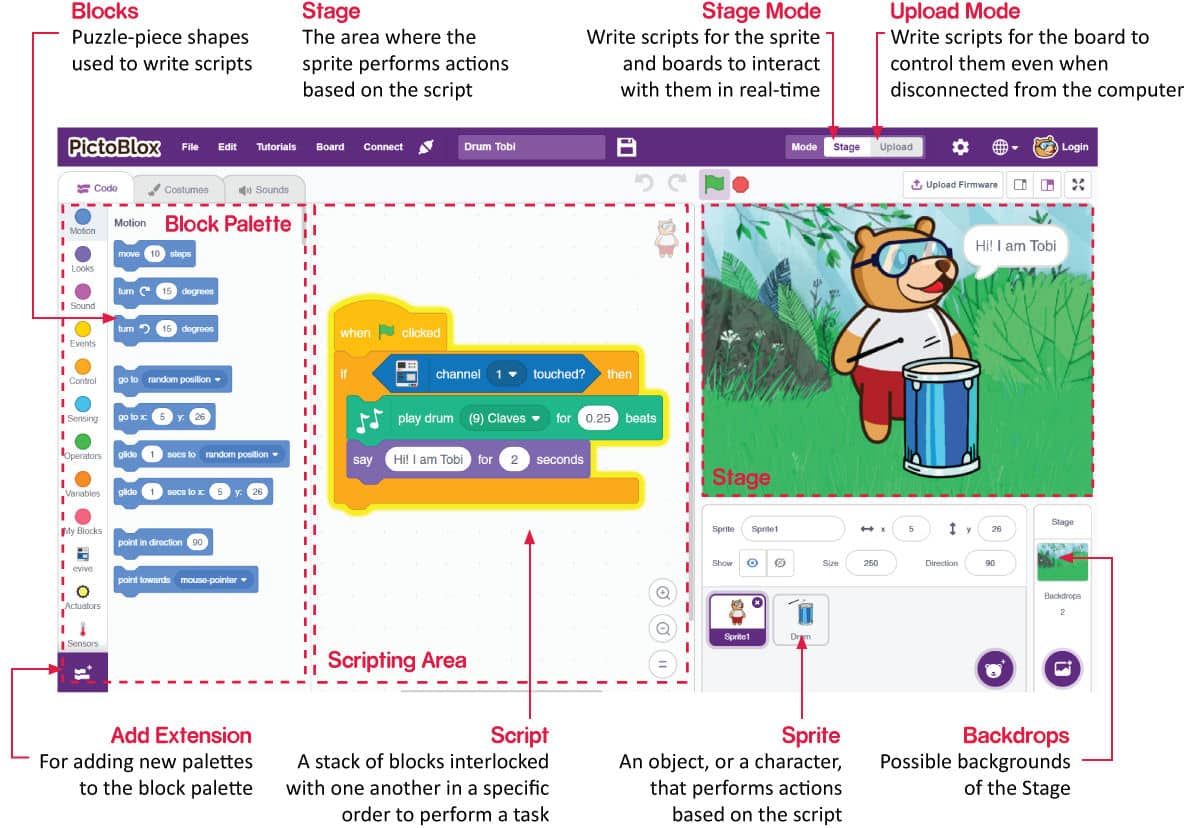
Sprite
The Sprite is a character or an object that performs actions according to the projects. Technically, a sprite is the face of your project. Here, in PictoBlox, Tobi the bear is your coding buddy. You can change the sprite if you wish to.
Stage
The stage is the area where your sprite performs the action. The background is known as the backdrop that makes your Stage beautiful. You can add the backdrop from the library, paint yourself, upload an image from the computer, or can even leave it blank.
Block
Block is the major element of all. You need to drag and drop the blocks in the scripting area. This simplifies or eliminates your need to worry about syntax.
Script and the Scripting Area
The script is what you can call your program or code. A combination of different blocks systematically makes your script. The script is where you decide what will your script do. You need to write your script in the Scripting Area.
Mode
Well, this is like the new dish on the platter. Unlike Scratch, you can work in two modes in PictoBlox:
- Stage Mode: In this mode, you can write scripts for the sprites and boards like Arduino Uno, Nano, Mega, and evive to interact with sprites in real-time. In case, if you disconnect the board in PictoBlox, you cannot interact anymore.
- Upload Mode: This mode allows you to write scripts and upload it to the board that you have selected so that you can use the board even when it is not connected to your computer.
Interfacing Arduino Uno to PictoBlox
To run the scripts written in PictoBlox, you must first upload it to Uno. Follow the procedure given below to interface Uno with PictoBlox.
- Connect Uno to your computer and open PictoBlox. If not yet installed, please refer to the Getting Started with PictoBlox tutorial HERE.
- In PictoBlox, go to the toolbar and click on the Board menu. Select Arduino Uno.
In doing so, the Arduino Uno, Actuators, Sensors, Display, and Dabble extensions will automatically appear in the Block palette. If not, add them from the extension library by clicking on the purple-colored Add Extension button in the bottom-left corner of the window. - Next, click on the Connect menu and from the fly-out menu, select the Port to which evive is connected e.g. COMXX or ttyXX. Once you select the port, the icon beside the Connect tab will become connected.
Activity: Make the Pin 13 LED Blink
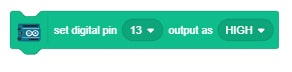
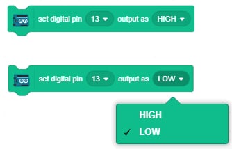
- To control the LED connected to pin 13, we’re going to use the set digital pin () output block.
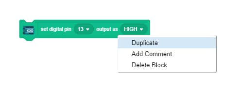
- We need two such blocks to make the LED blink. So, duplicate it by right-clicking on it.
- Set the output in this block to LOW.
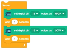
- Now, to control the speed of blinking, we’re going to use the wait block. Go to the Control palette and drag and drop one below each set digital pin () output block. //Gifs
- Now let’s stack all the blocks together.
- Observe that this script will run only once; in other words, the LED will turn ON, wait for a second, then turn OFF.
- To make the process continuous, we’ll use the forever block from the Control palette. It will run the script till the time you stop the script.
- To start any script, a hat block is necessary. Therefore, drag and drop When Arduino Uno starts up block above the script.
- Now, we need to upload it to the board. For that, switch to Upload mode by toggling this button. The Stage is replaced by an editor window with the equivalent C++ program for the script. To upload the code, click on the Upload Code button.
Once the upload is complete, the LED will start blinking.

Conclusion
In this tutorial, you learned a brief about PictoBlox, a graphical programming platform based on Scratch 3.0 and wrote a script make pin 13 LED blink.


