Introduction
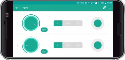
The Inputs Module of Dabble App has 3 input types:
- Potentiometer
- Slide Switch
- Tactical Switch
Each type has 2 inputs.
Potentiometer
The potentiometer is the first input type from left. It works similar to a real potentiometer, by providing a variable output value between 0 to 1023. You can change the value by rotating it. The value is sent to the hardware device when the potentiometer is moved.
Slide Switch
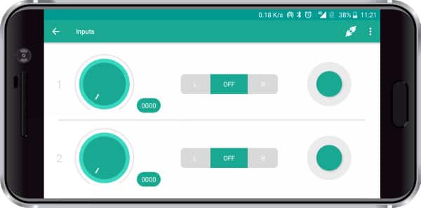
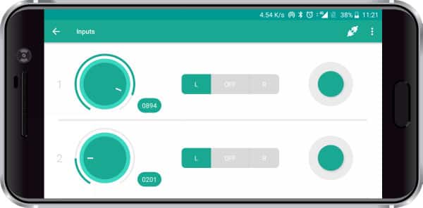
The Slide Switch is the second input type from the left. It has 3 states – Left, Right, and Off. By default when the module is opened the slide switch is in the Off state. You can change the state of the slide switch by clicking on the desired state.
At all times only one state will be active and the other two states will be inactive. The state of the slide switch is sent to Arduino, only when there is a change in the active position.
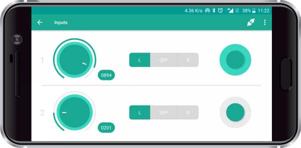
Tactile Switch
The tactile switch is the third and the last module in the Input module. It senses whether the user has pressed on the switch or not. It a momentary-type switch.
Arduino IDE Functions
Header
To include the Inputs module in the Arduino program, you have to include the following header:
#define CUSTOM_SETTINGS
#define INCLUDE_DABBLEINPUTS_MODULE
After defining the above mention headers, you have to include the dabble library:
#include <Dabble.h>
You can download the zip of Dabble-Arduino (for evive, Uno, Mega, and Nano) or Dabble-ESP32 depending on the board you are using.
Enabling Bluetooth Communication
To enable Bluetooth communication, you have to initialize serial communication using the following code:
For evive and Arduino Mega, Uno, and Nano
Dabble.begin(Baud_Rate);
Here Baud_Rate is the baud rate set for the Bluetooth module. With evive, you normally get 115200 baud rate modules.
For ESP32
Dabble.begin("Bluetooth_Name");
In place of Bluetooth_Name enter the name that you want to keep for Bluetooth of ESP32. The default name given in the library is “MyEsp32”.
Refreshing the data
To refresh the data that the device has got from the mobile app, you have to use the following line of code:
Dabble.processInput();
Functions
The following functions are available for the input module:
- Inputs.getPot1Value(): This function returns the potentiometer value 1 reading from the app. The returned value ranges from 0 to 1023.
- Inputs.getPot2Value(): This function returns the potentiometer value 2 reading from the app. The returned value ranges from 0 to 1023.
- Inputs.getSlideSwitch1Value(): This function returns the slide switch 1 state. These are the following possibilities for the returned value:
- 1 when the slide switch is in the left position.
- 2 when the slide switch is in the right position.
- 0 when the slide switch is in the center position.
- Inputs.getSlideSwitch2Value(): This function returns the slide switch 2 state.
- Inputs.getTactileSwitch1Value(): This function tells whether the tactile switch 1 is pressed or not. These are the following possibilities for the returned value:
- 1 when the switch is pressed.
- 0 when the switch is not pressed.
- Inputs.getTactileSwitch2Value(): This function tells whether the tactile switch 2 is pressed or not.
PictoBlox (Scratch) Blocks
You can access the controls of Inputs in the following ways:
Potentiometer: To use a potentiometer, you will need a reporter block “get potentiometer () value”. You can choose 1 or 2 from the drop-down of the block. It will return a value between 0 to 1023.
![]()
Slide Switch: To access a slide switch, you have to use a boolean block “is slide switch () ()?”
You can choose 1 or 2, Left or Right from the drop-down.
![]()
Tactile Switch: A boolean block “is tactile switch () pressed?” will enable you to access the tactile switch.
![]()


Examples
Arduino IDE
This example code prints the current state of all the potentiometers, slide switches, and tactile switches on Serial Monitor using the functions explained above. Board wise code is given below. You can also access the code by navigating to “File>>Examples>>Dabble>>” and selecting the “Inputs” example as per your board.
evive
/*
   DabbleInputs module of your smartphone consists of two potentiometers, two slideswitches and two push button.

   You can reduce the size of library compiled by enabling only those modules that you want to
   use. For this first define CUSTOM_SETTINGS followed by defining INCLUDE_modulename.

   Explore more on: https://thestempedia.com/docs/dabble/input-module/
*/
#define CUSTOM_SETTINGS
#define INCLUDE_DABBLEINPUTS_MODULE
#include <evive.h>
#include <Dabble.h>
void setup() {
  Serial.begin(250000);   // make sure your Serial Monitor is also set at this baud rate.
  Dabble.begin(115200);   //Enter baudrate of your bluetooth.Connect bluetooth on Bluetooth port present on evive.
}

void loop() {
  Dabble.processInput();             //this function is used to refresh data obtained from smartphone.Hence calling this function is mandatory in order to get data properly from your mobile.

  Serial.print("Pot1:");
  Serial.print(Inputs.getPot1Value());
  Serial.print('\t');
  Serial.print("Pot2:");
  Serial.print(Inputs.getPot2Value());
  Serial.print('\t');
  Serial.print("SS1:");
  Serial.print(Inputs.getSlideSwitch1Value());
  Serial.print('\t');
  Serial.print("SS2:");
  Serial.print(Inputs.getSlideSwitch2Value());
  Serial.print('\t');
  Serial.print("TS1:");
  Serial.print(Inputs.getTactileSwitch1Value());
  Serial.print('\t');
  Serial.print("TS2:");
  Serial.print(Inputs.getTactileSwitch2Value());
  Serial.println();
}
Arduino Mega, Uno, and Nano
/*
   DabbleInputs module of your smartphone consists of two potentiometers, two slideswitches and two push button.

   NOTE:
   1)For Arduino Mega Connect Bluetooth on Serial3 pins.
   2)For Arduino Uno/Nano library uses SoftwareSerial,hence pin 2 and pin 3 are used
   as RX and TX pins respectively on SoftwareSerial.Hence with arduino Uno
   follow below connections for bluetooth.
   UNO  - BLUETOOTH
   2    - TX
   3    - RX
   3)For Uno/Nano keep bluetooth Baudrate below 38400.


   You can reduce the size of library compiled by enabling only those modules that you want
   to use. For this first define CUSTOM_SETTINGS followed by defining INCLUDE_modulename.

   Explore more on: https://thestempedia.com/docs/dabble/input-module/
*/

#define CUSTOM_SETTINGS
#define INCLUDE_DABBLEINPUTS_MODULE
#include <Dabble.h>
void setup() {
  Serial.begin(9600);       // make sure your Serial Monitor is also set at this baud rate.
  Dabble.begin(9600);  //Change this baudrate as per your bluetooth baudrate. Connect bluetooth on digital pin 2(RX) and 3(TX) for Uno/Nano and on Serial3 pins for Mega.
}

void loop() {
  Dabble.processInput();   //this function is used to refresh data obtained from smartphone.Hence calling this function is mandatory in order to get data properly from your mobile.
  Serial.print("Pot1:");
  Serial.print(Inputs.getPot1Value());
  Serial.print('\t');
  Serial.print("Pot2:");
  Serial.print(Inputs.getPot2Value());
  Serial.print('\t');
  Serial.print("SS1:");
  Serial.print(Inputs.getSlideSwitch1Value());
  Serial.print('\t');
  Serial.print("SS2:");
  Serial.print(Inputs.getSlideSwitch2Value());
  Serial.print('\t');
  Serial.print("TS1:");
  Serial.print(Inputs.getTactileSwitch1Value());
  Serial.print('\t');
  Serial.print("TS2:");
  Serial.print(Inputs.getTactileSwitch2Value());
  Serial.println();
}
ESP32
/*
   DabbleInputs module of your smartphone consists of two potentiometers, two slideswitches and two push button.

   You can reduce the size of library compiled by enabling only those modules that you want to
   use. For this first define CUSTOM_SETTINGS followed by defining INCLUDE_modulename.

   Explore more on: https://thestempedia.com/docs/dabble/input-module/
*/
#define CUSTOM_SETTINGS
#define INCLUDE_DABBLEINPUTS_MODULE
#include <DabbleESP32.h>
void setup() {
  Serial.begin(115200);     // make sure your Serial Monitor is also set at this baud rate.
  Dabble.begin("MyEsp32");  //set bluetooth name of your device
}

void loop() {
  Dabble.processInput();             //this function is used to refresh data obtained from smartphone.Hence calling this function is mandatory in order to get data properly from your mobile.

  Serial.print("Pot1:");
  Serial.print(Inputs.getPot1Value());
  Serial.print('\t');
  Serial.print("Pot2:");
  Serial.print(Inputs.getPot2Value());
  Serial.print('\t');
  Serial.print("SS1:");
  Serial.print(Inputs.getSlideSwitch1Value());
  Serial.print('\t');
  Serial.print("SS2:");
  Serial.print(Inputs.getSlideSwitch2Value());
  Serial.print('\t');
  Serial.print("TS1:");
  Serial.print(Inputs.getTactileSwitch1Value());
  Serial.print('\t');
  Serial.print("TS2:");
  Serial.print(Inputs.getTactileSwitch2Value());
  Serial.println();
}
PictoBlox
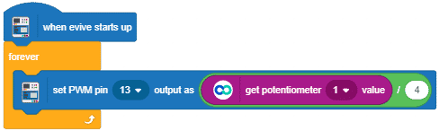
Example Potentiometer
Controlling PWM pins using potentiometers.
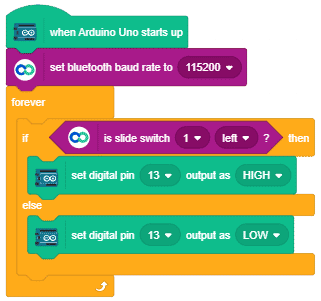
Example Slide Switch
Setting digital pins using slide switches.
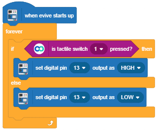
Example Tactile Switch
Setting digital pins using Tactile switches.
Depending upon your board type you can use different head blocks and along with it you also have to use “set bluetooth baudrate” as well, whereas the rest of the script remains the same. Currently, PictoBlox supports evive and Arduino Uno, Nano, and Mega boards. Support for the ESP32 board will be added soon.


