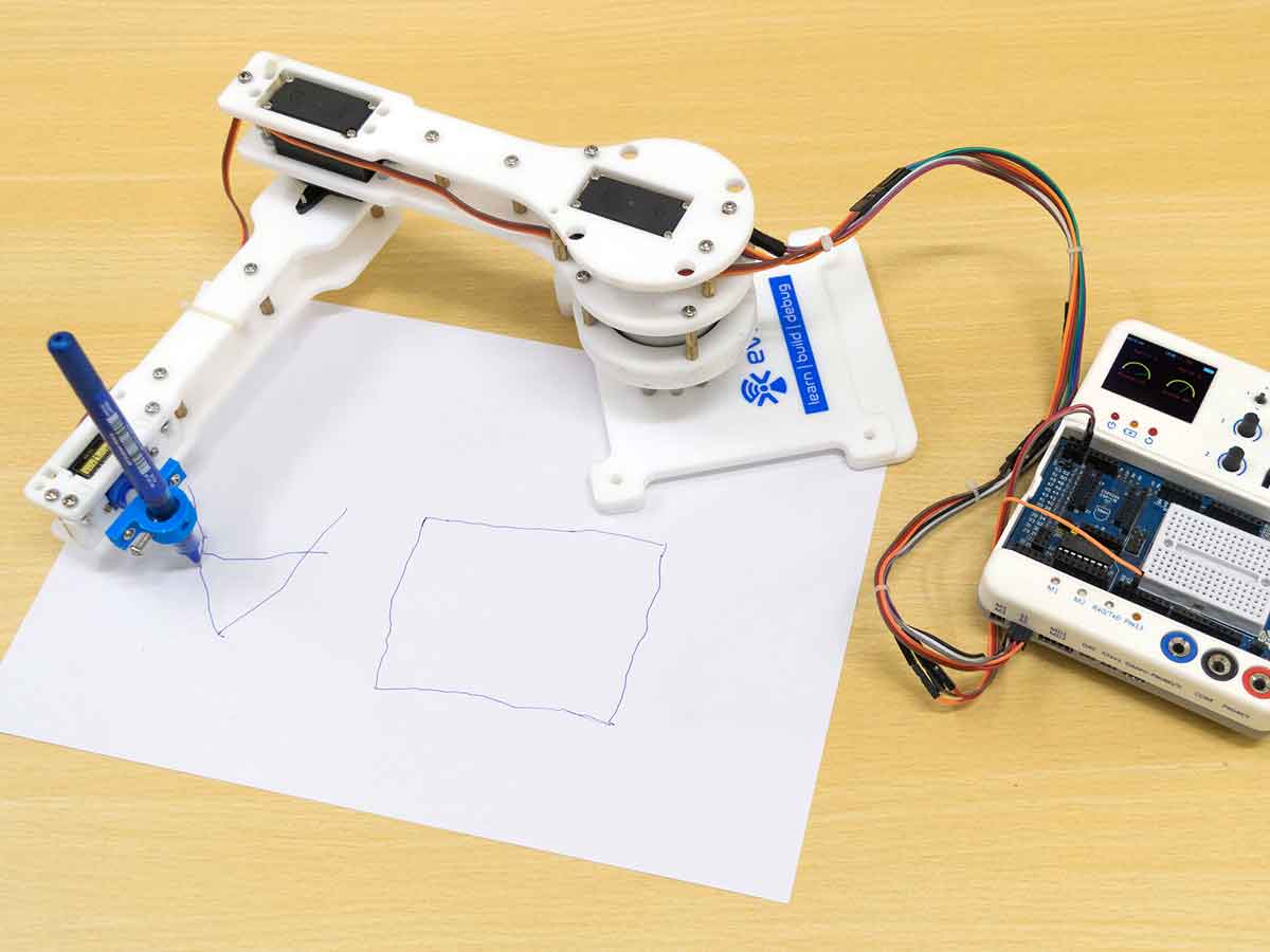
Introduction
This is a three degree of freedom robotic arm with a pen holder as its end effector. You can code this robot to draw anything, write your name, sketch your face and much more.
Assembly of the Robot
- Mount servo horn on the top inner bearing disc using self-threading M2 (“M2” represents a diameter of 2mm) screws of 8mm length. These screws can be found in servo accessories. Be careful about holes you are mounting the horn on (use holes closer to disk center).


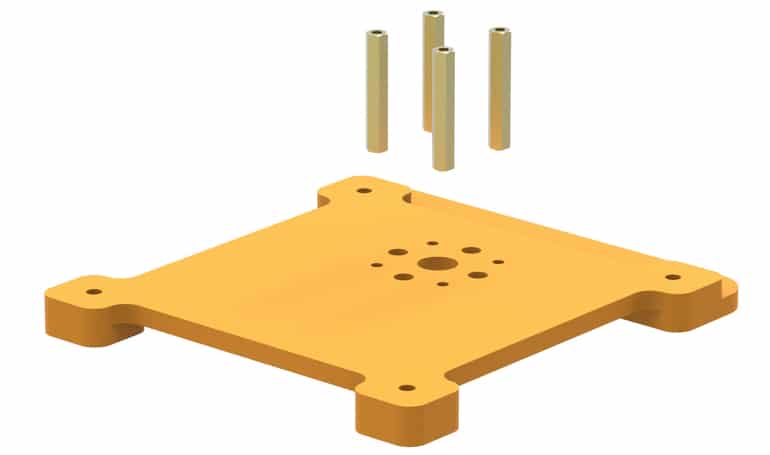
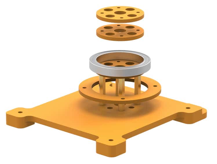
- Place 30 mm stand-offs on the base. Fasten using M3 bolts of 8mm length.

- Take the bottom outer bearing disc and slide it over standoffs.

- Mount bottom inner bearing disc on stand-offs. Align the disc such that smaller holes are in line with the stand-offs.

- Put the bearing on top of the bottom inner bearing disc. Observe how disc supports the bearing from beneath.

- Next, place the two middle inner bearing discs. These will perfectly fit inside the bearing.
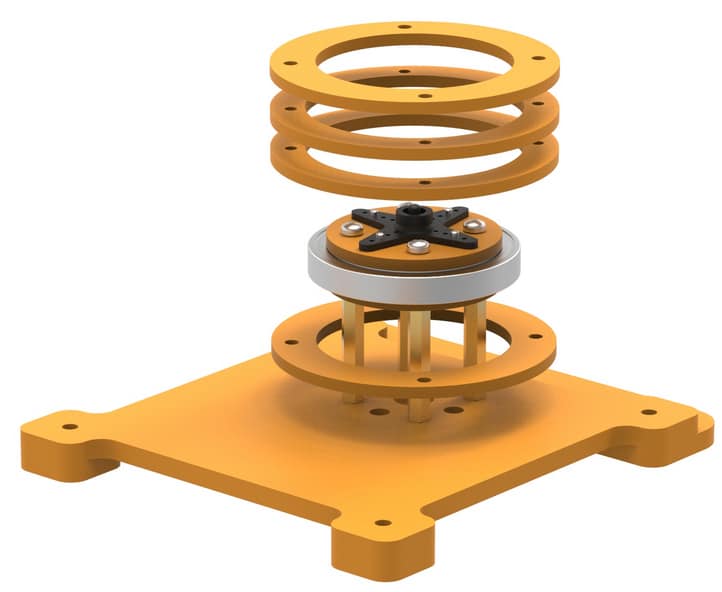
- Seat the “servo horn & top inner bearing disc” assembly on top of bearing as shown. Make sure all smaller holes in these discs are aligned since we will fasten them all together using 20mm M3 bolts.

Note1: Do understand that it was necessary to slide down the bottom outer bearing disc earlier. You won’t be able to do it now due to diameter differences.

Note2: Observe how the bearing has been clamped between the top and bottom inner bearing discs. 
- Place the middle outer bearing discs first and then top outer bearing disc as shown. The middle discs will have a larger inner diameter compared to the top and bottom ones. The inner diameters of the middle discs will be equal to the bearing’s outermost diameter.
- Slide up the bottom outer bearing disc, align the holes in the discs and stack them.
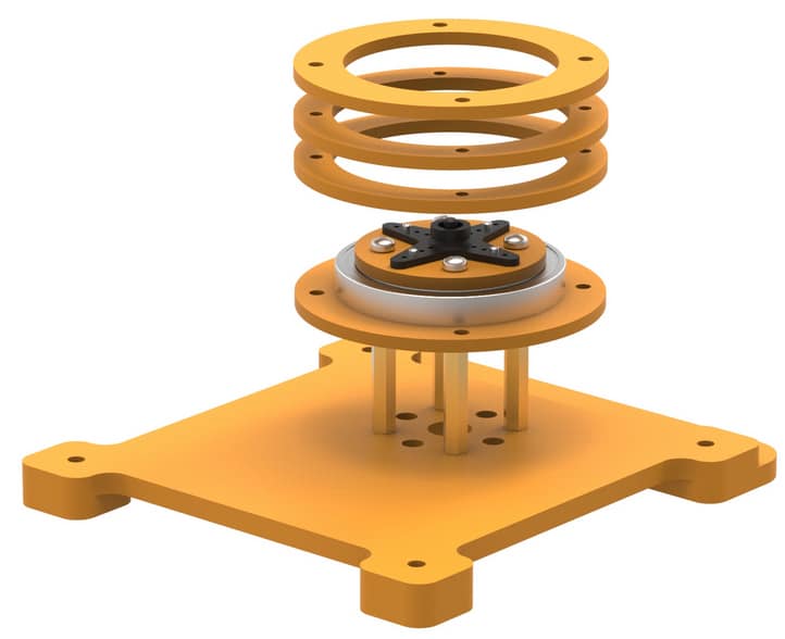
Again, see how the bearing is sandwiched because the top and bottom bearing discs have a smaller inner diameter compared to the bearing’s outermost diameter. 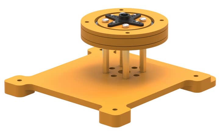
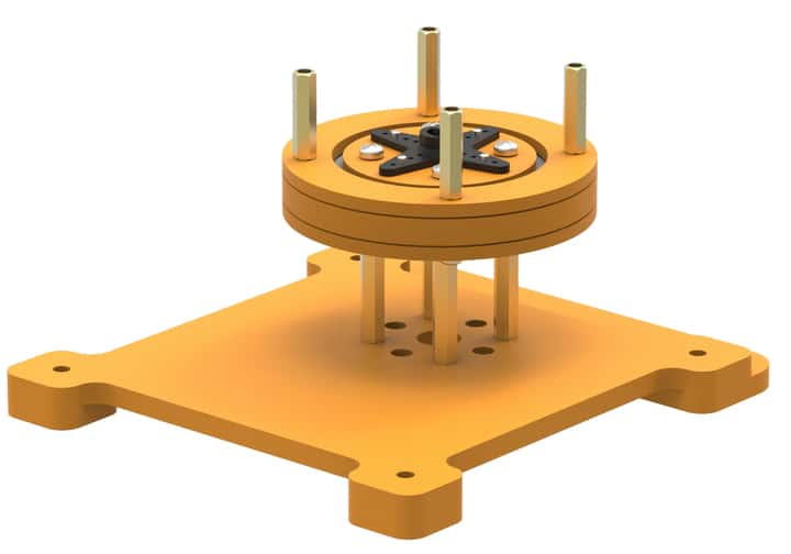
- Place 20 mm stand-offs on the top and fasten the M3 bolts of 20mm length from the bottom. Your base is completed now.


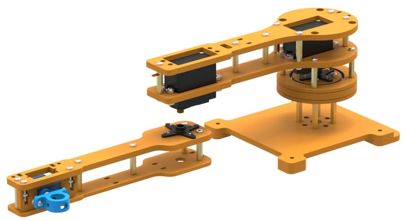
The base assembly should look like this upon completion.
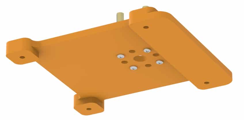
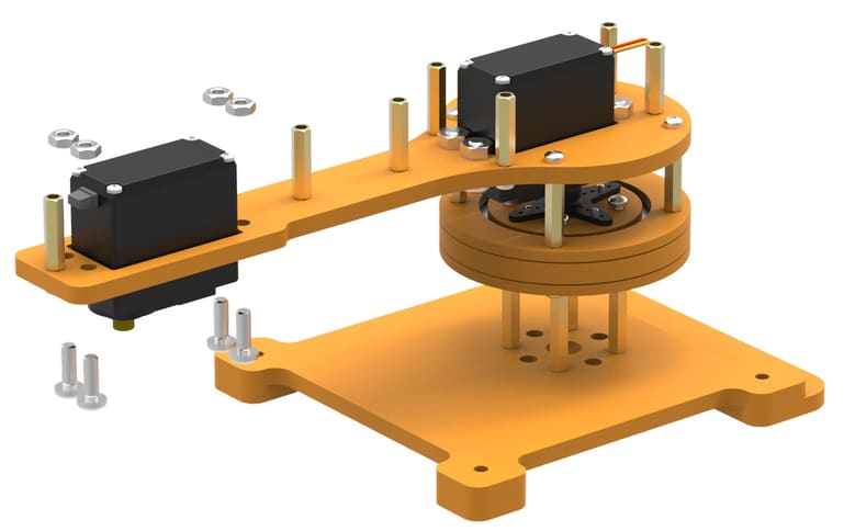
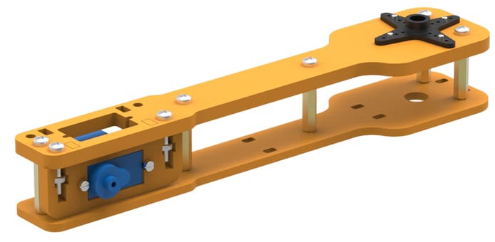
- Place servo motor into the slot available on racquet-shaped link 1. Be careful about the positioning and the orientation of the servo. Have a careful look at the illustrations.
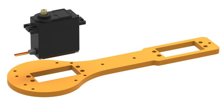
- Fasten the servo to the link using M4 bolts of 16mm length and nuts.

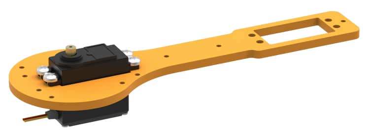
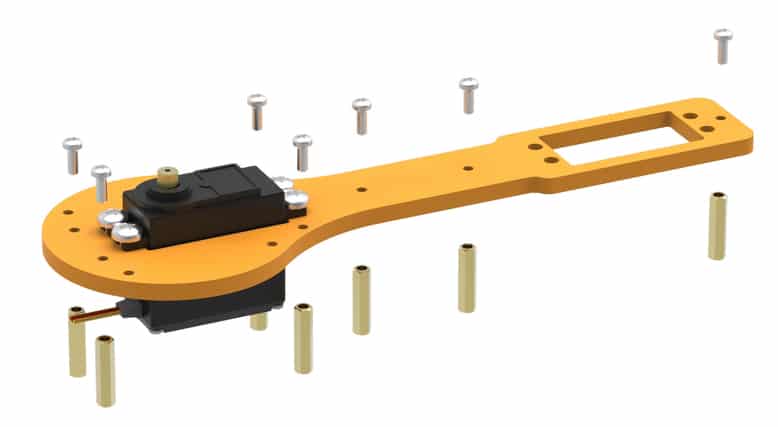
- In the figures, you see the head of the servo pointing upwards. Don’t let this confuse you; the head actually goes into the slot in the horn. We will come to this again, for now, attach M3 bolts of 8mm length and 20mm standoffs to the link as shown in the illustrations below.

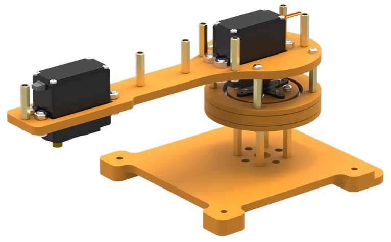
This is the orientation in which we will place the completed link upon our base. Note the free holes through which we will drive the screws to fix it to the base. 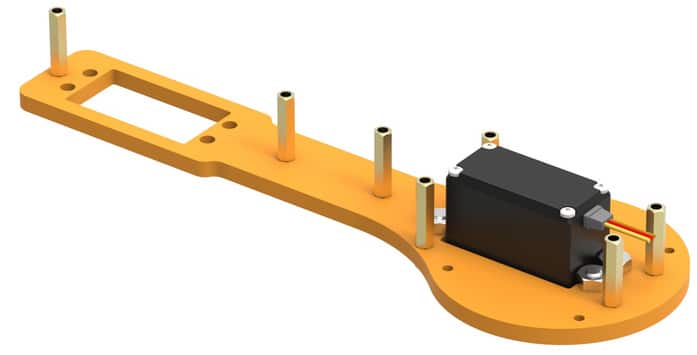
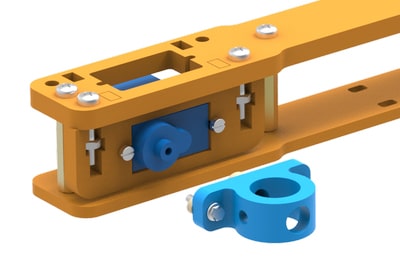
- Place this assembly on the base as shown & fasten using M3 bolts of 8mm length.
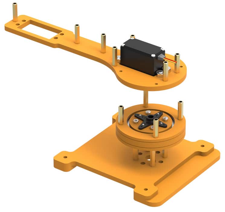
Keep in mind that you’ve set servo at 90 degrees before assembling (connect the servo to evive, go to control > servo and set servo at 90 degrees). 

- Observe how the head of the servo goes into the servo horn. We have to ensure proper locking between the servo head and servo horn. To do this, drive a bolt into the center of the horn (find this in servo accessories) through the bottom of the base (through the large hole) and fasten it.
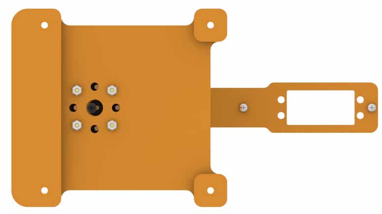
It is important to ensure that your servo motor does not move vertically and exhibits only rotary motion while in operation.
- Push the servo up the second slot in this link.
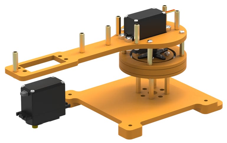
- Fasten servo to the link using M4 bolts of 16mm length and M4 nuts.
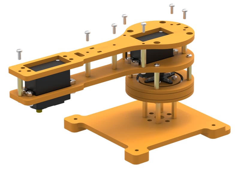
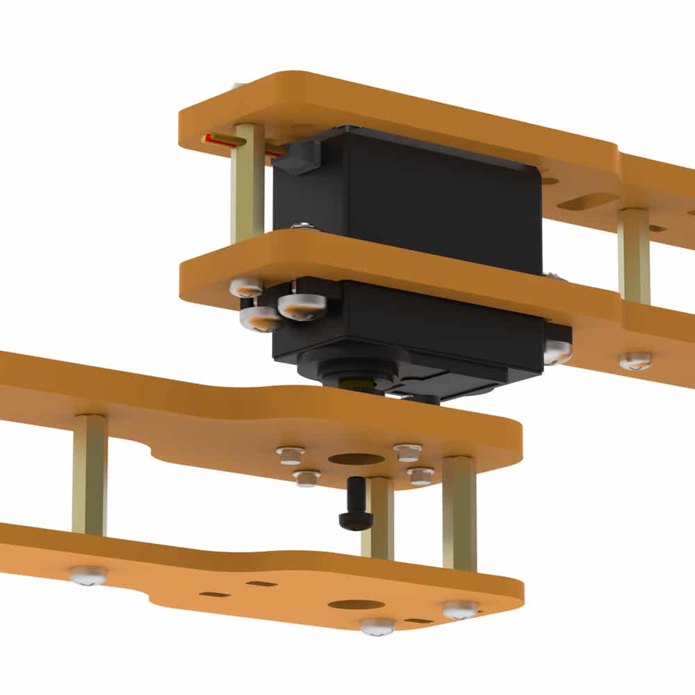
- Place racquet-shaped link 2 upon the arrangement as depicted in the following figures.

Notice the larger holes in racquet-shaped link 2. They are for ease of disassembly and re-assembly. You can easily drive a screwdriver through the holes if you want to fasten or loosen the screws right below the holes.
- Insert M3 bolts of 8mm length wherever required.

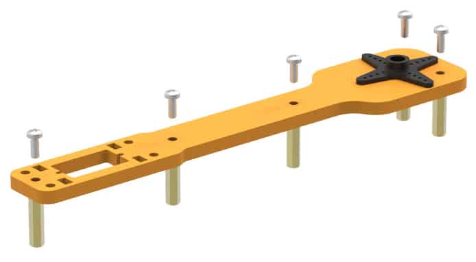
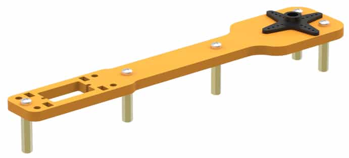
- Now, assemble the second link. Attach another servo horn on link 2 and fasten using self-threading M2 screws. This link is different from supporting link as it has a slot for another servo. Refer to the figures.

- Attach 20 mm stand-offs at the positions shown, then fix these standoffs with M3 bolts of 8mm length.
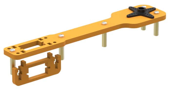
- Fit the servo holder into rectangular slots provided on link 2 from below. Refer to the figures and see which rectangular slots to fix the holder in.
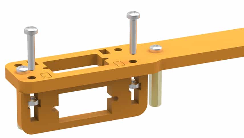
- Insert M3 nuts into the slots provided in the servo holder and fasten with M3 bolts of 12mm length. Refer to the figures below.

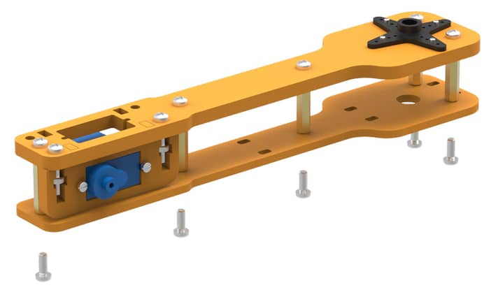
- Fix the micro servo in the slot provided in the configuration shown. Be careful about the position and orientation of the servo head and fasten using M2 bolts of 12mm length and nuts as shown.


- Attach support link and fasten it to the standoffs using 8mm M3 bolts.
This is how our second link looks. The servo horn will be attached to the mini servo’s head in our first link (step 16).
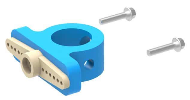
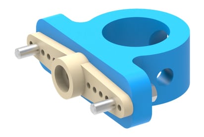
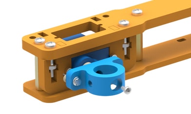
- Now, we will assemble the pen holder. Note that there is a free servo head in the second link assembled. This servo will support the pen holder through a micro horn. Attach the micro horn to the pen holder using self-threading M2 bolts of 8mm length (from micro servo accessories) as shown.
- Fasten the pen holder to the second link by driving a screw (from servo accessories) through the servo horn as done in step 15. Keep in mind that the micro servo is set at 90 degrees as done in step 14.
- Recall the free servo horn on the second assembled link. Set the servo angle to 180 degrees as done in step 14. Now, we will attach it to the servo head on the first assembled link and will fix them together by fastening it using the bolt provided in servo accessories.

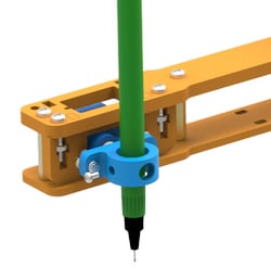
- We are almost done now. The only thing which remains is to fix a pen. Proceed by placing it in the slot given at a suitable height.

- Fasten M3 bolts of 8mm length to hold the pen in the pen holder.
Note: Please ensure all fasteners are well-tightened, the robot might stay wiggly otherwise. 
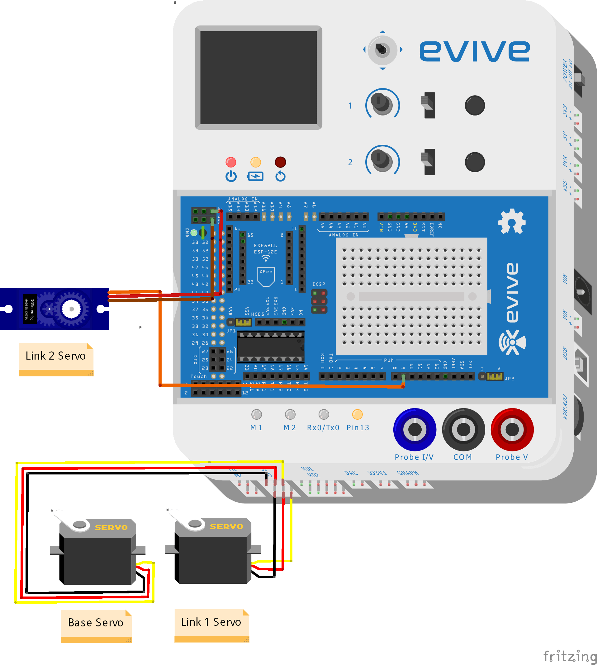
Circuitry of the Robot

Note: Ensure that all the servos are properly connected and there are no loose wires, this might otherwise affect the performance of the arm during operation. Use cable ties for wire management.
Arduino Code
In this program, we are controlling the robotic arm using potentiometers and slide switch.
- Base Servo is controlled using potentiometer 1
- Link 1 Servo is controlled using potentiometer 2
- Link 2 Servo is controlled using slide switch 1
This program also shows the variable voltage on the screen. <>
Caution: The robotic arm should operate at 6V using a 2A power supply.
Libraries: TFT_ST7735
#include <Servo.h>
#include <TFT_ST7735.h>

double angle_rad = PI/180.0;
double angle_deg = 180.0/PI;
double BaseServoAngle;
double Link1ServoAngle;
double VariableVoltage;
TFT_ST7735 lcd = TFT_ST7735();
Servo servo_44;
Servo servo_45;
Servo servo_9;

void setup(){
    lcd.init();
    lcd.setRotation(1);
    lcd.fillScreen(0);
    pinMode(A0+9,INPUT);
    servo_44.attach(44); // init pin
    pinMode(A0+10,INPUT);
    servo_45.attach(45); // init pin
    pinMode(40,INPUT);
    servo_9.attach(9); // init pin
    pinMode(A0+7,INPUT);
}

void loop(){
    BaseServoAngle = analogRead(A0+9);
    BaseServoAngle = ((BaseServoAngle) * (180)) / (1023);
    BaseServoAngle = (180) - (BaseServoAngle);
    servo_44.write(BaseServoAngle); // write to servo
    Link1ServoAngle = analogRead(A0+10);
    Link1ServoAngle = ((Link1ServoAngle) * (180)) / (1023);
    Link1ServoAngle = (180) - (Link1ServoAngle);
    servo_45.write(Link1ServoAngle); // write to servo
    if(digitalRead(40)){
        servo_9.write(90); // write to servo
        lcd.setCursor(10, 55);
        lcd.print("Pen Servo Angle: 90 Deg");
    }else{
        servo_9.write(0); // write to servo
        lcd.setCursor(10, 55);
        lcd.print("Pen Servo Angle: 0 Deg ");
    }
    VariableVoltage = analogRead(A0+7);
    VariableVoltage = (VariableVoltage) * (0.0381);
    lcd.setCursor(10, 10);
    lcd.print("Voltage: ");
    lcd.print(VariableVoltage);
    lcd.print(" V   ");
    lcd.setCursor(10, 25);
    lcd.print("Base Servo: ");
    lcd.print(BaseServoAngle);
    lcd.print(" Deg   ");
    lcd.setCursor(10, 40);
    lcd.print("Link 1 Servo: ");
    lcd.print(Link1ServoAngle);
    lcd.print(" Deg   ");
    delay(50);
}
Conclusion
This project demonstrates the assembly and programming of a three degree of freedom robotic arm with a pen holder as its end effector. Servo motors are used to control and power the robot. The design provided is designed to be compact and cost-effective, and can easily be programmed to draw various shapes and patterns. The completed robot has the capabilities to be adapted and modified for various applications including production and manufacturing.