Introduction
LDR (wikipedia) are light sensitive devices most often used to indicate the presence or absence of light or to measure the light intensity. An LDR can be applied in light-sensitive detector circuits and light-activated and dark-activated switching circuits.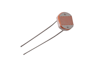
How does the LDR sensor work?
The resistance of a photoresistor decreases with increasing incident light intensity. In other words, it exhibits photoconductivity. A photoresistor is made of a high resistance semiconductor. In the dark, a photoresistor can have a resistance as high as several megohms (MΩ), while in the light, a photoresistor can have a resistance as low as a few hundred ohms.
Variation in resistance with changing light intensity
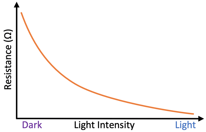
The most common type of LDR has a resistance that falls with an increase in the light intensity falling upon the device (as shown in the image above). You can therefore see that there is a large variation between these figures. If you plotted this variation on a graph you would get something similar to that shown by the graph shown above.
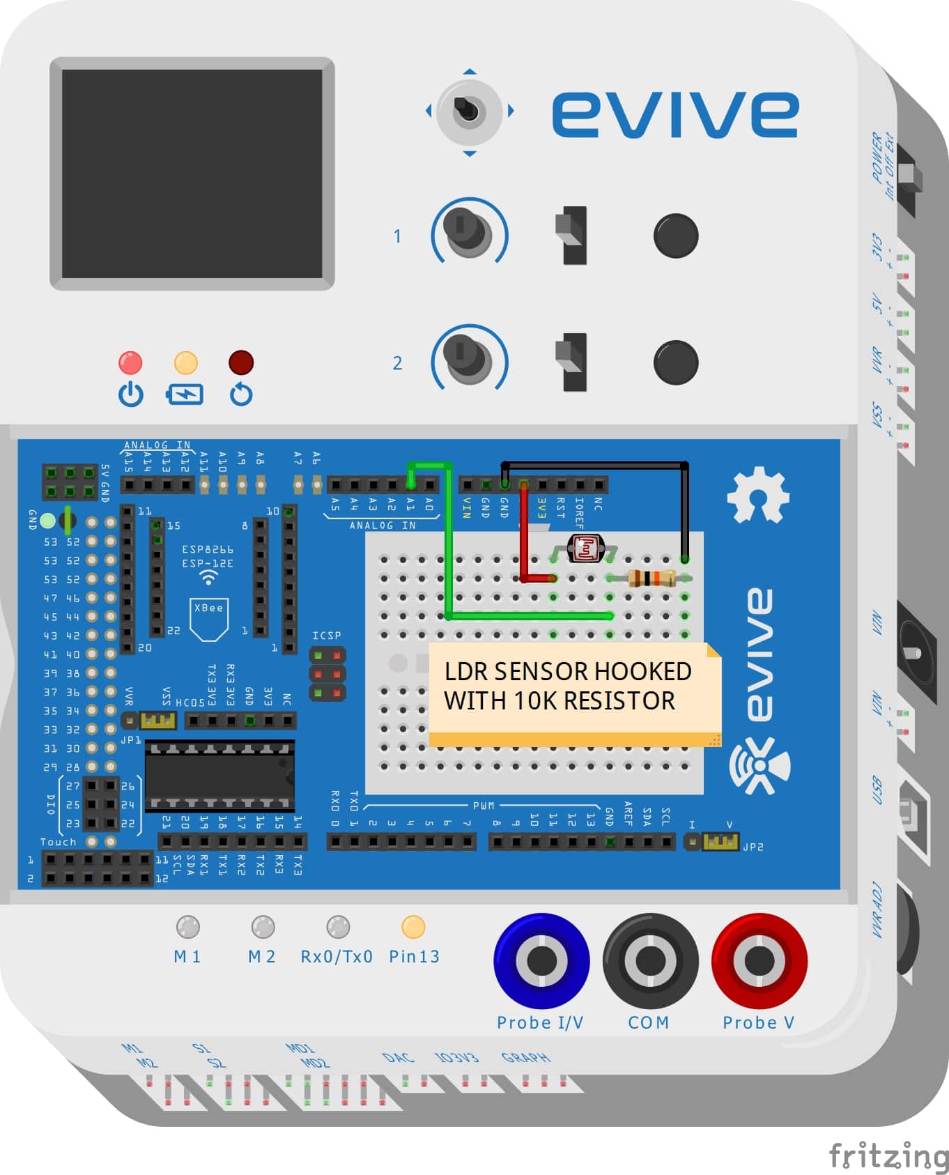
Setting up the circuit for the LDR sensor
The circuit of the LDR sensor is explained below
- One end of LDR is connected through jumper wire(red wire ) to the 5V power supply in the evive board.
- Another end of LDR is soldered with a 10K resistor. Through the common junction of LDR and 10K resistor, a jumper wire is taken and hooked into the analog input(here we have used A1 pin number in the evive board) of the evive board.
- The free end of the resistor is grounded with the help of a jumper wire.
Arduino Code
The following Arduino code controls the led state using the LDR sensor.
/***********************************************************************
 *
 * Description: In this arduino code we will control the led state using
 * LDR sensor.When the LDR sensor reaches a certain threshold value the led
 * will be turned on.
 *
 * AUTHOR: Chetan Vashishtha
 *
 * DATE:15/05/2018
 *
**************************************************************************/
#include<evive.h>
int sensorPin = A0; // select the input pin for the LDR
int sensorValue = 0; // variable to store the value coming from the sensor
int ledPin =13;// select the input pin for LED

void setup() {
pinMode(ledPin, OUTPUT);
Serial.begin(9600);
Serial.println("LIGHT'S OFF");// here you ca input any text
Serial.println("LDR TEST");
tft.fillScreen(ST7735_BLACK);
}

void loop(){
  sensorValue = analogRead(sensorPin);
  Serial.println(sensorValue);
  if (sensorValue <500)
  {
    digitalWrite(ledPin,HIGH);
    delay(100);
  }
  else
  {
    digitalWrite(ledPin,LOW);
    delay(sensorValue);
  }
}
Output
The final circuit is shown in the figure.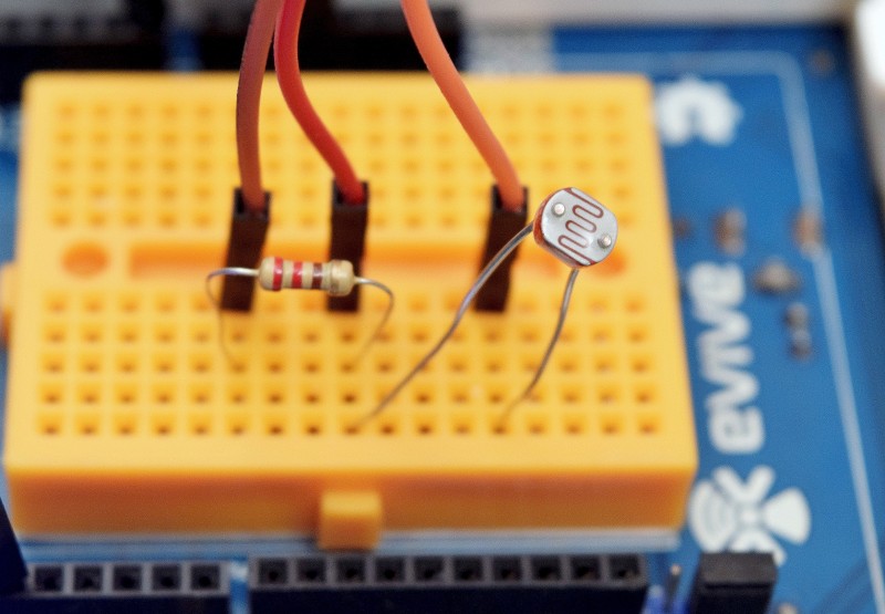

Conclusion
In conclusion, this lesson has shown how to build a simple light–sensitive circuit using an LDR sensor and an Arduino. The circuit was set up and the Arduino code was written to detect changes in light intensity and turn the LED on or off accordingly. The lesson has provided a clear understanding of the working of an LDR and its applications.


