
Introduction
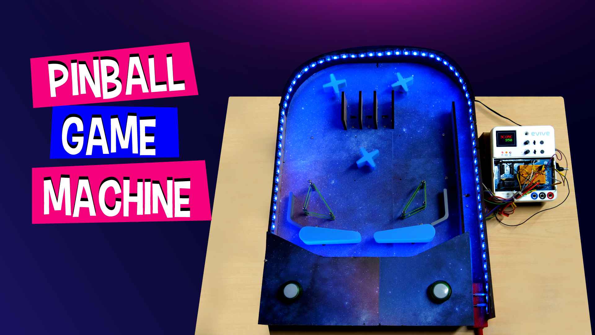
And we’re back to make your weekend merrier with another one of the most popular arcade games – the Pinball machine! In this project, we’ll show you how you can make your own Pinball machine easily at your home. And it’s going to be nothing short of super duper fun! You’ll be needing the evive Starter Kit, some laser-cut parts, some colors and papers to decorate your machine, and loads of DIY-ing! So, gather your friends, put on your DIY-ing vest, and let’s go Pinball-ing!
We’ve used PictoBlox – our versatile graphical programming platform with advanced capabilities – to write the code. You can download it from HERE.
The Cutouts
Before we start making our all-time favorite Pinball Machine, we need to have some cardboard or MDF cutouts and some 3D printed parts. You can find the MDF design here and the STL files here.
Let’s first understand the components that we need for the Pinball Machine.
- The Control Panel
- The Supports (x 2)
- The Score Walls (x 4)
- The Base
- The Boundary Walls (x 2)
- The Front Wall
- The Small Wall
- The Launch Wall
- The Drain Wall
We have prepared the entire machine on MDF Sheets so that it can last forever for us to play.
Getting the Playfield Ready
Decorating the Base Plate
Take the base cutout and decorate it. We are going with a space theme and thus took a printout of a beautiful space image and glued it to our base. Once glued, cut the extra paper out and give the base a nice finish. You can go with any theme you want.
Once the base is as beautiful as it should be, make holes that were already on the base plate.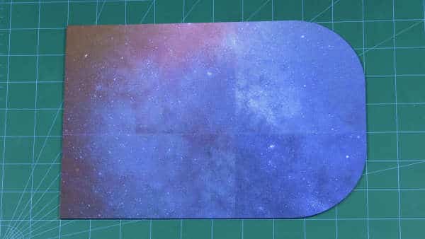
Adding the Boundary Walls
Once you have the base ready, its time to make the walls of our Playfield. Take the boundary walls and place it the base plate, make sure that the holes on both the plates are aligned. Once aligned fix the two walls on the base plate using M3 nuts and bolts.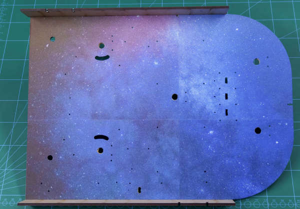
Now, the side boundaries are guarded it’s time to secure the front side. Take the front wall and attach it to the left boundary wall and the base using M3 nuts and bolts. Wonder why it is not attached to the right wall?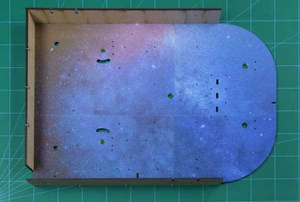
Because that’s where we will have our Launchpad.
Now, what is Launchpad? Read the next step to know more.
Getting the Launchpad Ready
As the name suggests, launchpad in our space theme will be used to launch the Rocket… wait not rocket, the ball of our Pinball machine.
Take the small wall(7) and fix it at 90 on the base plate using M3 nuts and bolts.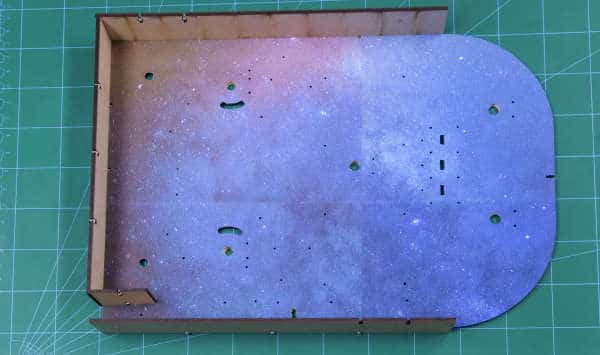
As soon as the game gets OVER, the balls directly roll down to the drain. This is where the end of the game is. The drain will directly open up in the launchpad. Thus, take the drain wall and attach it to the base such that it is both attached to the small wall and the left boundary.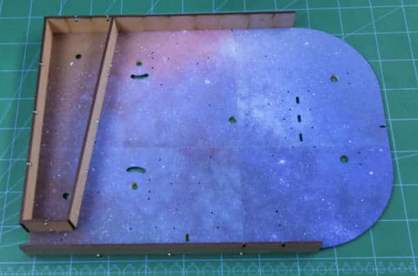
Now, take the launch wall and fix it next to the right boundary wall but at some distance. Make sure that there is a small space between the drain wall and launch wall. As it is the gate from where your ball will roll from the drain section to the launchpad.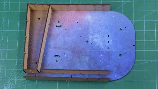
Adding the Score Walls
How are we going to count the scores, well the score walls are here to save the day! Take all the four score walls and attach it to the base plate at the top on the assigned positions using M3 nuts and blots.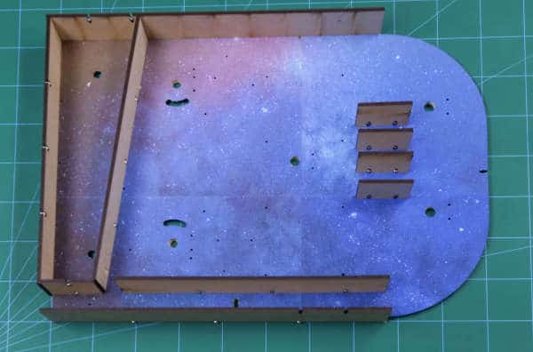
They are just MDF plates, why are we calling them the Score wall? Meet us where we start making our playfield smarter.
Completing the Boundary Walls
Now, our playfield is almost secured from all the sides except the back. Here, we can use MDF Sheet, but we won’t. We want the back wall to have a perfect curve. Thus, glue a thick foam sheet of your choice to the base plate using Hot Glue. 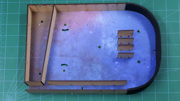 Now, even if you launch the ball at a great speed, it won’t escape. It will hit the boundary wall and roll down in the field area.
Adding the Supports
To make the ball roll down the playfield easily, we need to add some inclinations to the playfield. Take the supports and attach them to the playfield using M3 nuts and bolts.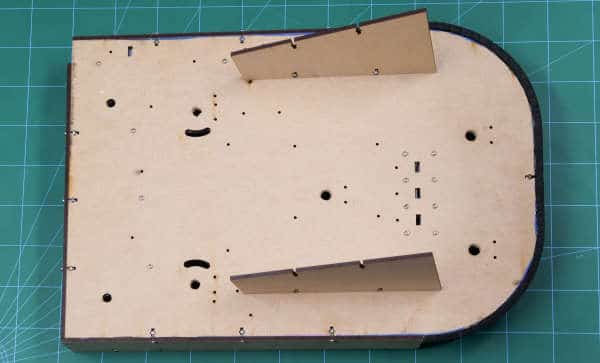
Gluing the Incline Wall
You may notice that there is a small corner where the boundary and the drain walls meet. This place may surely corner your ball, thus we will add a small piece of acrylic sheet that will help the ball smotthly roll to the drain.
With this, your playfield is ready to roll(the ball).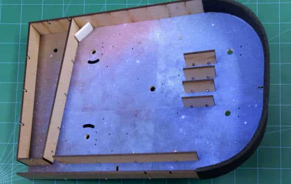
Making the Playfield Smarter
Mounting the DC Motors and the Limit Switches
Now, playfield in the pinball is never empty, there are bumpers, flippers, kickers and so many other components.
But bumpers and flippers are the ones that need to rotate continuously. Even though not always 360 in case of flippers. Thus, we need to add DC Motors for the same.
We are going to add 2 flippers and 3 bumpers into our playfield. Thus attach the DC motors to the space given using M3 nuts of 20mm length and bolts.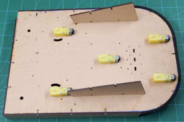
The bumpers do not need any other component, then DC Motors. But, flippers do. We need to restrict the flipper movements so that it turns only so much that they redirect the ball to the playfield. So, for that, we will be gluing limit switches next to the DC motors of flippers. You may notice that comparatively a longer curve hole is given on the base plate for the flippers. Attach the limit switches at the ends of the holes on both the sides.
Once you press the control button, the DC motor starts rotating, the flipper touches the upper limit switch, DC Motors starts rotating in the opposite direction until the flipper touched the lower limit switch. The process will repeat every time you press the corresponding control switch.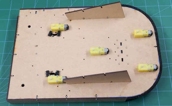
Adding the IR Sensors
The normal pinball is ready, but you need to make it smaller so that every target you hit counts. Thus, we are going to add IR Sensors.
We are going to use 5 IR sensor in total:
- One at the launchpad
- Three in Score walls
- One at the drain wall
Attach the IR Sensor of the launchpad and the Score wall as given in the figure below: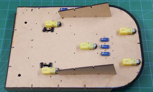
Once the ball passes through the IR at the launchpad, the game starts.
The walls are called the score walls or targets as you can earn points if your ball passes through them. Every time the balls passes through any score wall, the IR sensor detects it and add the score assigned to that wall in your total score.
The center lane gives you a 1000 and the side ones give you 500. You can change the score assigned in the code.
IR at the drain wall indicates that the game is over. 
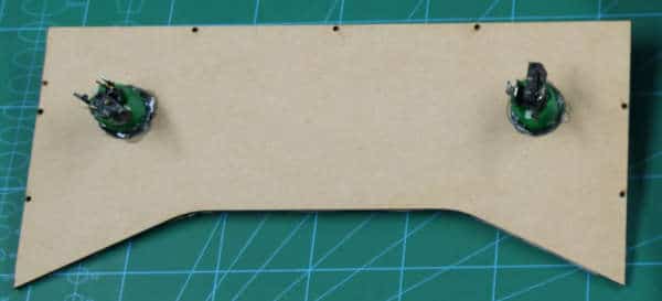
Attaching the Control Buttons
We need something to control the flippers. Well, we are going to use control buttons for the same. Control buttons are nothing but the arcade gaming switches. Take the control panel and in the holes given attach the arcade switches. One for the left flipper and one for the right.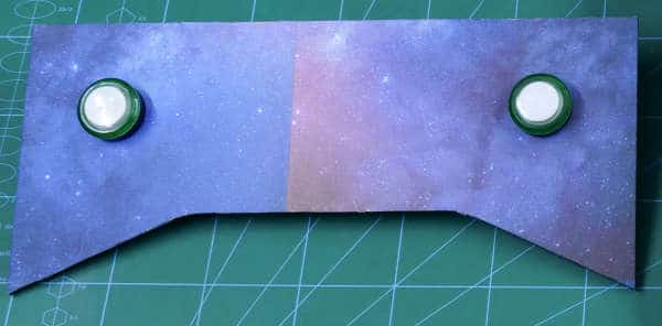
Adding the RGB LED Strip
Pinball without lights are nightmares or even an arcade game without the lights are a fail. Thus lets glue the RGB LED strip at the boundaries of the playfield.
We will not just let them glow the way we want. We will make them glow the way we want. Thus, every time the game starts the playfield should turn green.
And it should turn red when the game is over. Also, it should change the color each time the ball passes through the score walls.
Adding the Plunger
We cannot just flick the ball from the launchpad to the playfield. The plunger will help you do that. We have 3D printed a plunger with a hole in it to pass rubber through it. And as the rubber is long enough attached it to the front wall and the right boundary wall using Hot glue.
Thus, the more you pull it, the ball will be launched in the playfield with that force.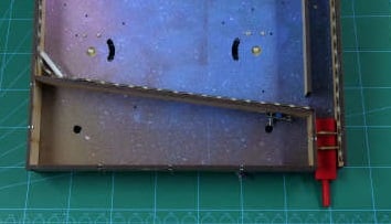
Fixing the Control Panel to the Playfield
Once the plunger is fixed, fix the control panel onto the playfield using M3 nuts and bolts.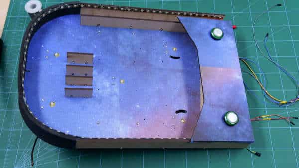
Adding details to the Playfield
Mounting the Side Lane Walls
We have 3D printed L-shaped side lane walls that will direct your ball to the flipper once your ball enters into the lane.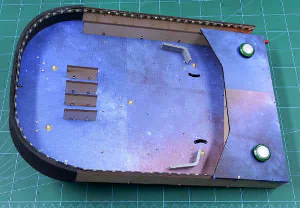
Mounting the Bumpers
Bumpers are there to add difficulties in the game. Fix the 3D printed bumpers on to the shaft of the DC motors. They will rotate continuously pushing the ball away.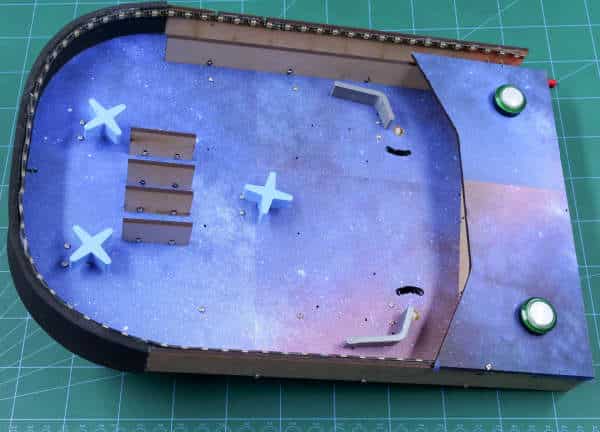
Adding Flippers
Flippers are real heroes that make you score. Attach the flippers to the shaft of the DC motor. They will redirect the ball into the playfield once the balls hit them and you have pressed the corresponding control button at the right time.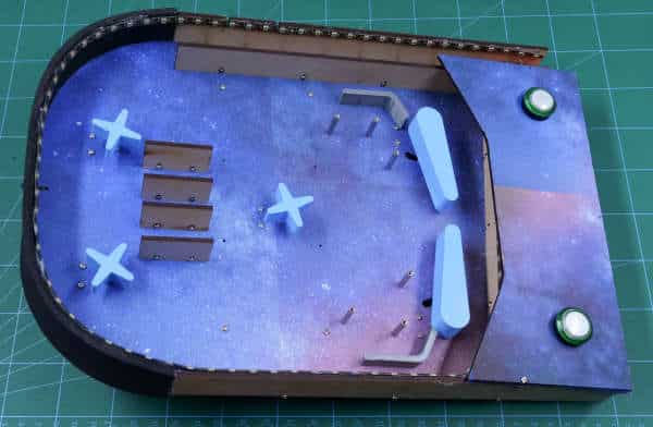
Adding Kickers on the Playfield
They are the once that are used to reflect the balls. Attach 3 standoffs on each side and wrap rubbers around it. Thus, as soon as the ball will hit them, they will propel the ball horizontally.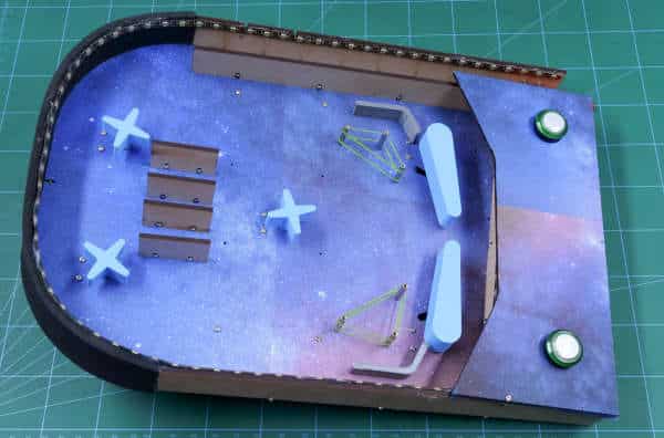
Making the Connection
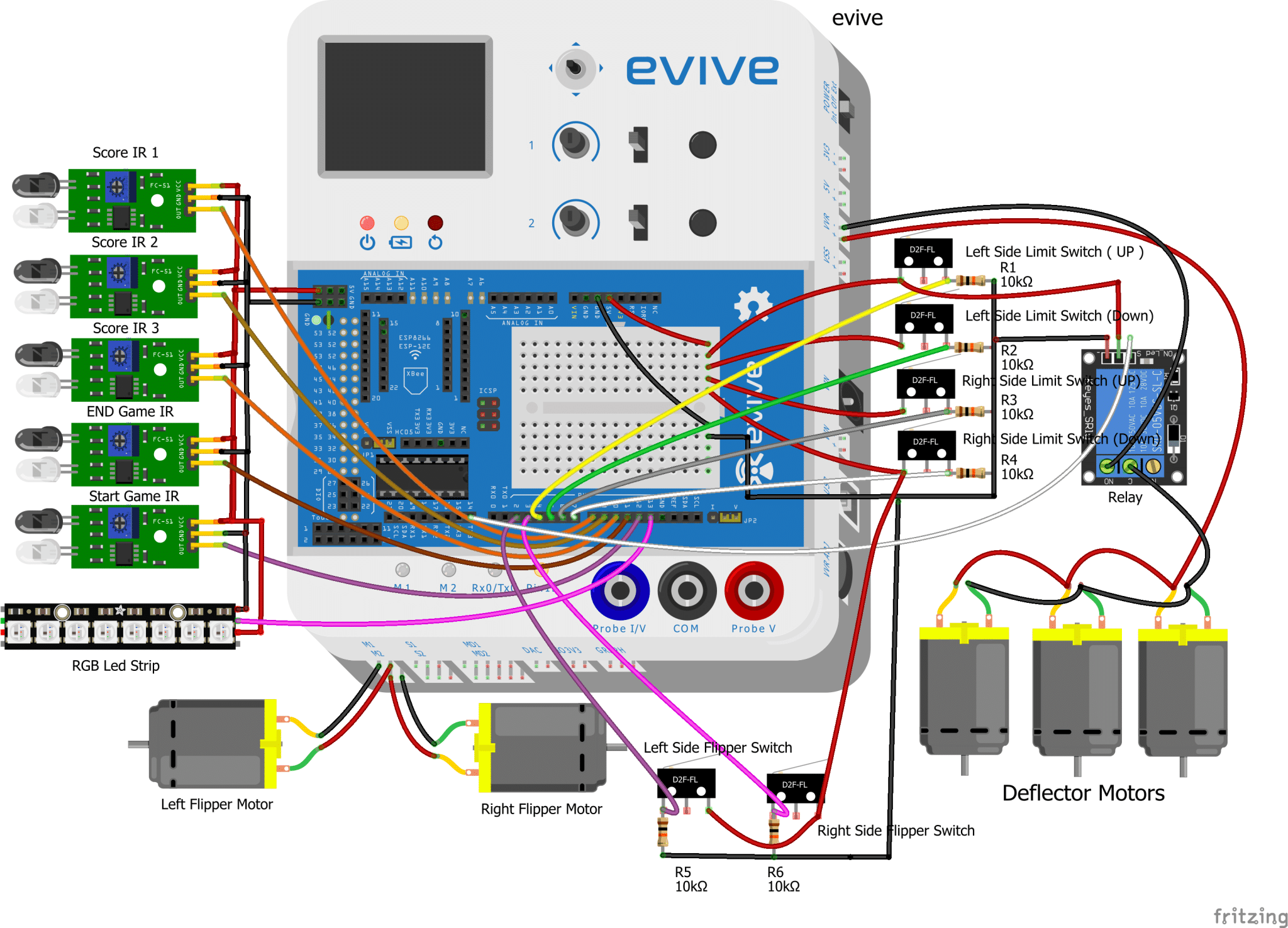
Now, we cannot wait to play the game so let’s make the connection for the same. Well, there are lots of connections. Follow the steps given below and you are done.
- Connecting the IR Sensors
- Score 1 IR Sensor(signal pin) to Digital Pin 8 of evive
- Score 2 IR sensor(signal pin) to Digital Pin 9 of evive
- Score 3 IR sensor(signal pin) to Digital Pin 10 of evive
- Drain Wall IR sensor(signal pin) to Digital Pin 11 of evive
- Launchpad IR sensor(signal pin) to Digital Pin 12 of evive
- Now connect VCC and GND of all the IR sensor to VCC and GND of evive
- Connecting the RGB Strip
- Connect the RGB LED strip to Digital Pin 13 of evive
- Connecting Flipper Motors
- Left Flipper Motor to M1 port of evive
- Right Flipper Motor to M2 port of evive
- Connecting the Flippers
- Connect the “NC” terminal of Left Side Flipper Switch to Digital Pin 2 of evive and 10K ohm resistor, and connect another end of 10k ohm resistor to GND of evive, also connect “COM” terminal of Left Side Flipper Switch to VCC of evive
- Similarly, connect the “NC” terminal of Right Side Flipper Switch to Digital Pin 3 of evive and 10k ohm resistor, and connect another end of 10K ohm resistor to GND of evive, also connect “COM” terminal of Right Side Flipper switch to VCC of evive
- Connecting the Bumper Motors
- Connect all the 3 Bumper motors in parallel and connect its one end to VVR(+) pin and another end to “COM” terminal of Relay, then connect “NO” terminal of the relay to VVR(-) pin of evive
- Connecting the Limit Switches
- Connect “NC” of Left Side Limit Switch(Up) to VCC of evive and COM terminal to Digital Pin 4 of evive and to GND via 10K ohm resistor
- Connect “NC” of Left Side Limit Switch(Down) to VCC of evive and COM terminal to Digital Pin 5 of evive and to GND via 10K ohm resistor
- Connect “NC” of Right Side Limit Switch(Up) to VCC of evive and COM terminal to Digital Pin 6 of evive and to GND via 10K ohm resistor
- Connect “NC” of Right Side Limit Switch(Down) to VCC of evive and COM terminal to Digital Pin 7 of evive and to GND via 10K ohm resistor
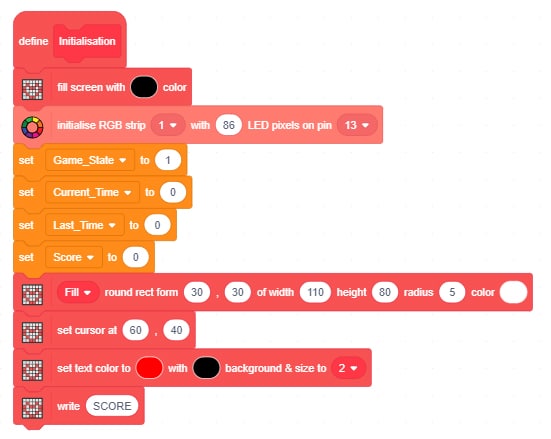
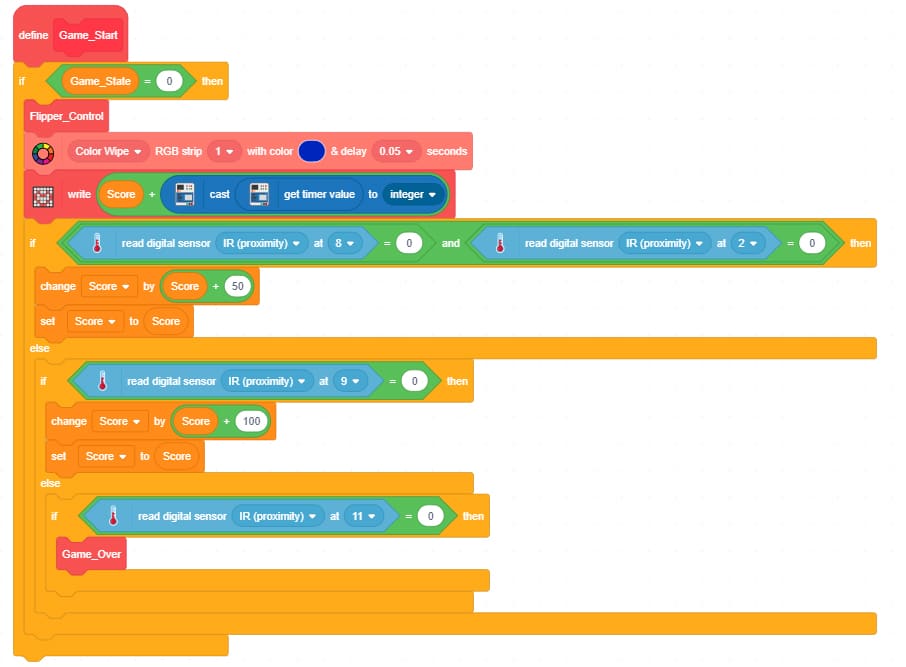
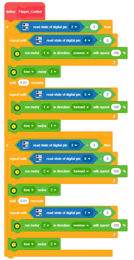
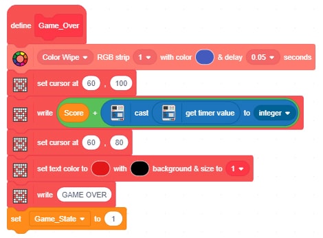
Coding the Rules
Upload the following PictoBlox script to evive and make your leaderboard ready.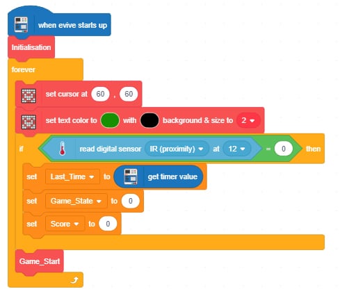
Conclusion
With this, your DIY Pinball machine is all set. Ready. Set. Play!