


When you turn on Quarky for the first time, it runs the Getting Started Program to check if everything is working properly, like the LED display, buzzer, motor movement, tactile switches, and touch sensor.
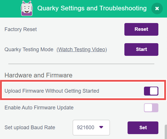
This program also runs when you update the firmware, but you can choose to skip it by enabling “Upload firmware without Getting Started” in Quarky Settings.
Learn more here: Getting Started with Quarky
Yes! You can enable the “Upload Firmware Without Getting Started” option in Quarky Settings in PictoBlox.
Once this is turned on, the Getting Started Program will be skipped after uploading the firmware, and you can start working in Stage Mode immediately without running the hardware check.
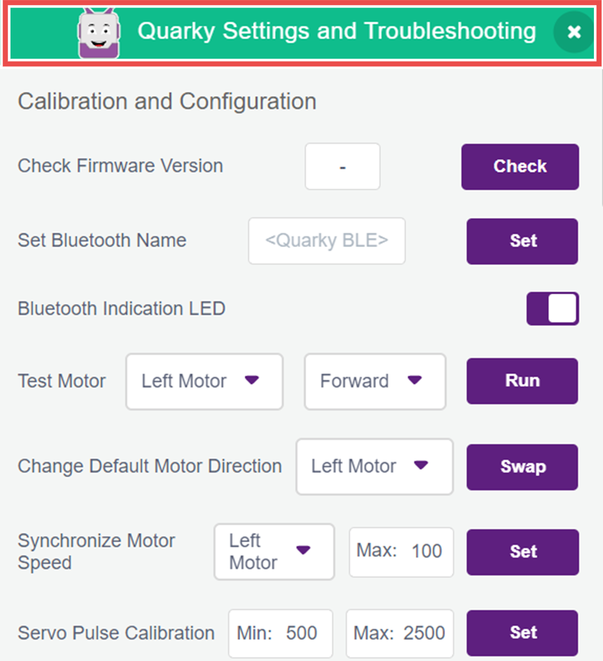
Quarky Settings allows you to test and control Quarky’s components without coding. You can inspect motors, touch sensors, buttons, display, and IR sensors. Additionally, you can reset or update firmware, view the firmware version, customize the Bluetooth name, and enable options like skipping the introductory program.
It’s a handy tool to make sure Quarky is working just the way you want!
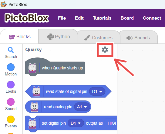
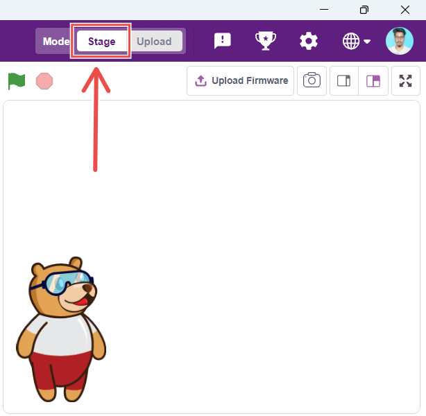
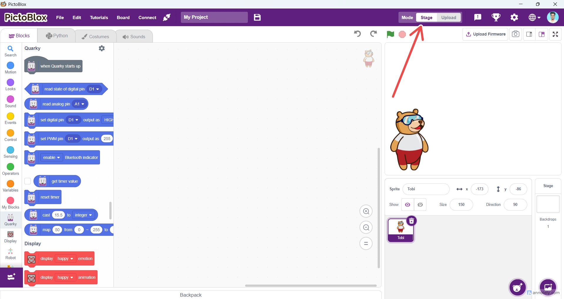
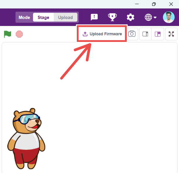
To access Quarky Settings in PictoBlox, refer to the screenshot below.
![]()
Long press the right button on Quarky for 3 seconds. The Bluetooth name will be displayed.
Long press the left button for 5 seconds. This will put Quarky into Getting Started mode.
Follow these steps to skip the getting started mode in quarky:
Below is a short description of the configurations and calibrations you can perform using the Quarky settings/Quarky Debug Extension:
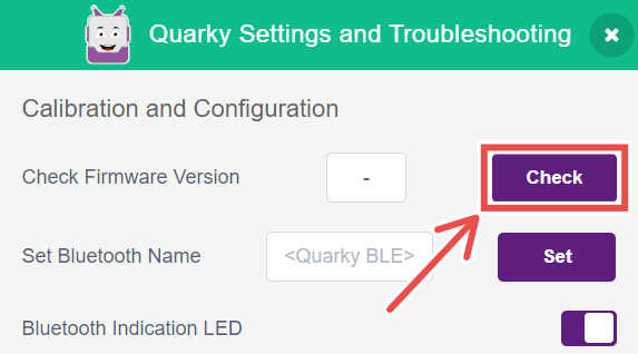
4.1 Firmware Version Check:
4.1.1 By clicking on the check button, the board will send its firmware version, which will be displayed in the empty field (In this example, the firmware version is 4.1).
4.1.2 Version check will be useful for debugging the problems faced by the user. You can determine if any feature that is not working on the board is supported by the firmware version present in the board or not. Example: Ultimate Robots’ extension is not supported on versions < 4.1
4.1.3 Versions 3 and 4 correspond to the previous C++ based firmware, whereas Quarky Python firmware begins from 4.1 onwards. The latest firmware version in PictoBlox v6.2.0 is 5.0.
4.2 Bluetooth Settings
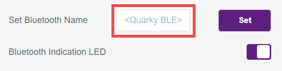
4.2.1 On powering ON, Quarky shows its Bluetooth connectivity status through blue/green color on the bottom right LED of the display (BLUE: Bluetooth disconnected, GREEN: Bluetooth connected). Users can turn off this indicator using the toggle button to the right of the Bluetooth Indication LED option.
4.2.2 The default Bluetooth name of Quarky follows the format “Quarky wxyz” where the wxyz digits stand for the last four digits of the Bluetooth MAC address of the board. Users may change the Bluetooth name to any 12 digit string, including numbers and special characters.
4.3 Motor Calibration
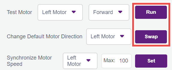
4.3.1 Select the motor you want to test and the direction it should turn, and click on the Run button. Verify if you think it is running in the intended direction, if that is not the case then click on Stop.
4.3.2 Now, to change the direction of the incorrectly configured motor, select it in the dropdown of the Change Default Motor Direction option & click the swap button. Now you can again run the motor using the Test Motor option, and you will find the direction to be corrected.
4.3.3 Quarky will remember this configuration even after power is turned off and will be forgotten only on erasing the flash.
4.4 Servo Pulse Calibration

4.4.1 Servos are adjusted to the desired angle using PWM signals. The signals generally have 50Hz frequency and the angle of the servo is set by the width of the pulses, i.e.,0° corresponds to a 500 µs pulse width, whereas the maximum angle, 180°, corresponds to approximately 2500 µs.
4.4.2 These pulse width values are given just as an example, and it may vary according to the servo used. So to calibrate your servo’s minimum and maximum position, you can set their values in the Min. and Max. Field and click on Set button. You can check the calibration result by running the set servo to [x] angle from the robot palette.
4.5 RGB Test
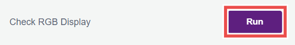
4.5.1 In case you want to test the proper functioning of the RGB LEDs on your Quarky, press the run button and a LED test sequence will run on your board which you can observe to validate the RGB LEDs. The test sequence would be as follows:
4.5.2 Complete grid would follow the pattern of colors: Red, Green, Blue and then White.
4.5.3 The white color pattern will go from low brightness to high, and then from high to low.
4.5.4 Finally, the rainbow pattern will run on the board.
This above sequence will help you identify any faulty LED present on the board.
4.6 IR Sensors Test
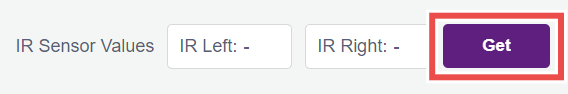
4.6.1 If you want to get the continuous readings of the onboard IR sensors, then you can use this option as the continuous analog sensor data streamed from the board will be visible here and you could use the same to calculate your threshold values for the sensors.
4.7 Output and Input (GPIO) Pins Testing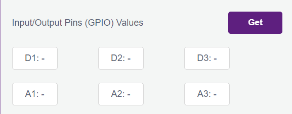
4.7.1 If you feel like your digital pins output commands are not working properly, then you can test the hardware pins using the blink option. On clicking the ON button, the corresponding pin will go high and low periodically and you can test with an LED or multimeter if the hardware pin state is actually changing or not.
4.7.2 Similarly, to test some sensor’s input values to the hardware pins, you can stream the values read by the Quarky pins continuously by clicking the Get button. You can validate the proper functioning of your Quarky input pins this way, and also calculate the threshold for your analog sensors.
4.8 Touch Calibration
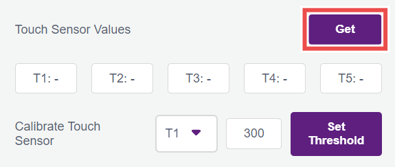
4.8.1 You can check if the touchpads on Quarky are working properly using the Get button beside Touch Sensor Values, this will start filling the T1, T2, etc. fields with the analog values of the touch pins that are being communicated to PictoBlox by Quarky.
4.8.2 Try touching the pads and notice the drop in the readings, and you can then set the touchpads threshold accordingly using the Calibrate Touch Sensor option.
4.9 Push Button Calibration
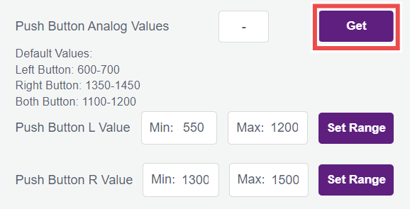
4.9.1 Pressing the Left and Right push buttons on Quarky sends analog values to PictoBlox which checks the range in which this value falls under and based on that it declares if the left or right push button is pressed.
4.9.2 If push buttons are not working on Quarky, users can check the same using the analog values fetching option and pressing the buttons and observing the values. If the value is shown as just “-”, it means the board is not responding (check if firmware is uploaded on Quarky properly), if the value is stuck at 0, it may suggest a problem with the hardware.
4.9.3 The analog values may differ between boards and the user may wish to change this range for L and R push buttons, and he can do the same using the other two options below the analog values.
4.10 Factory Reset
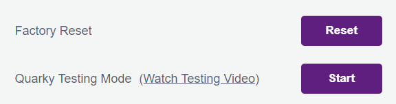
In case the user wishes to reset the configurations set through the Quarky settings, they can do so by clicking on the Factory Reset button which will delete all the saved Bluetooth name, pulse width, touch threshold, etc. from the board without having to erase the flash which achieves the same.
4.11 Enable auto firmware update
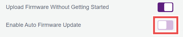
4.11.1 When this option is enabled, PictoBlox will automatically detect the Quarky firmware when connected via USB and update it if required. This ensures that Quarky always runs the latest firmware without manual intervention.
4.11.2 When disabled, PictoBlox will not automatically update the firmware. Users must manually upload the firmware using the “Upload Firmware” button.
4.12 Ultrasonic Sensor Test
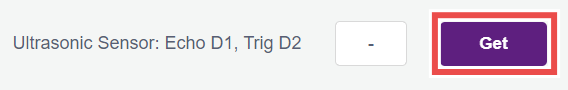
4.12.1 You can validate the proper functioning of your Ultrasonic sensor by connecting the echo and trig pins of your ultrasonic sensor to D1 and D2 pins, respectively. On pressing the Get button, you will continuously get the distance measured by the ultrasonic sensor if the sensor is working correctly.
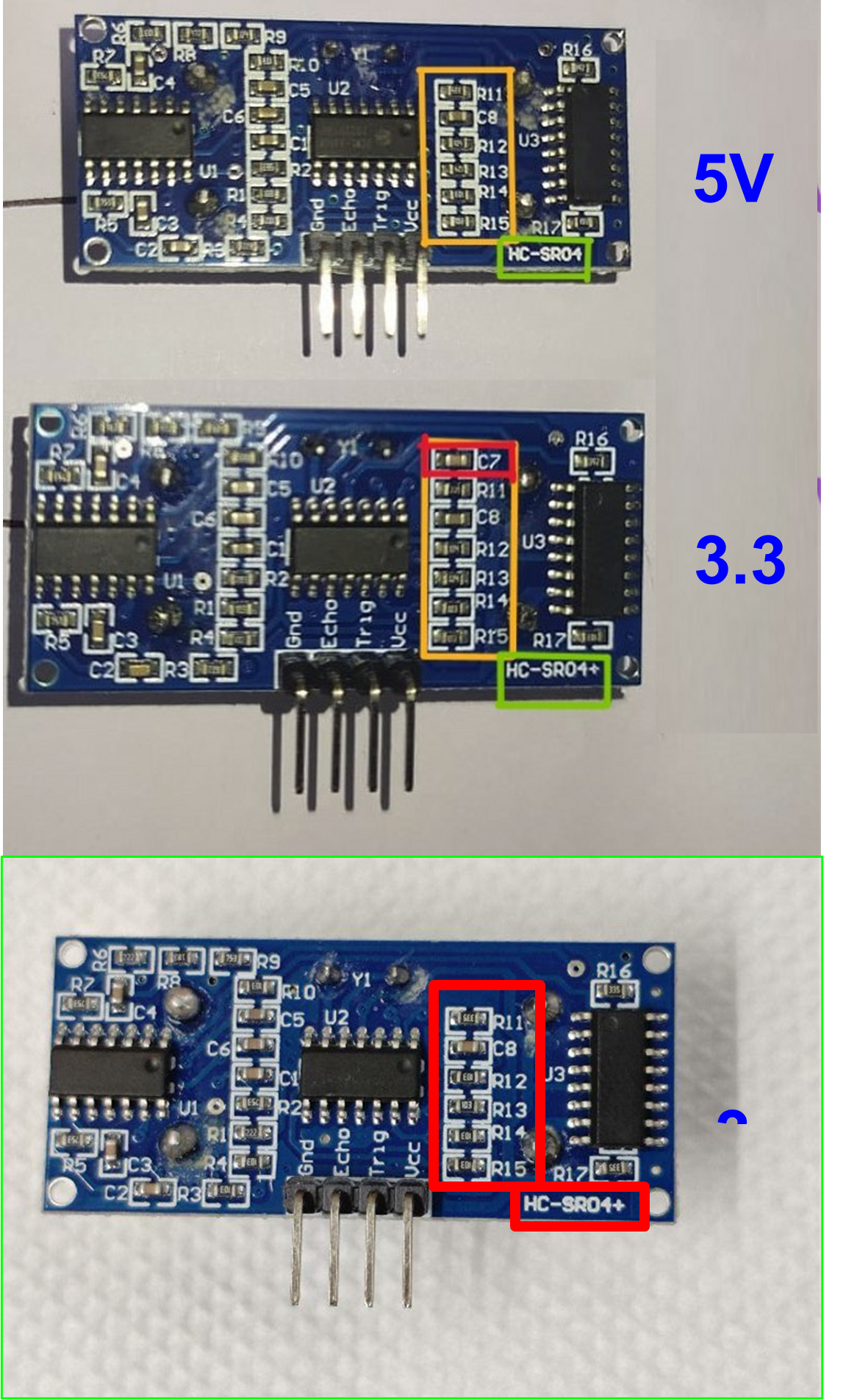
4.12.2 In case you don’t get the distance, please try checking if the sensor you are operating is a 3.3V compatible sensor or not, as Quarky does not support 5V logic level sensors.
4.12.3 Distinguishing 3.3V and 5V Ultrasonic sensors
4.12.4 Check for the part number on the sensor (depicted by the Green box in the image below). Search for the text HC-SR04+, which means it is 3.3V compliant. If the part number is HC-SR04, then it is a 5V version and won’t work with Quarky.
4.12.5 You can also distinguish the 3.3V and 5V sensors by looking at the backside of your sensor and differentiating the presence of C7 capacitor (depicted by the Red highlight box in the image below):
Quarky is made using high quality materials and goes through strict testing to ensure it’s durable and reliable. Still, in case something goes wrong, we offer the following warranty coverage:
6.1 Quarky Board: 1 year warranty for manufacturing defects
6.2 Battery: 6 month warranty
6.3 Consumables (like motors, ultrasonic sensors, plastic parts): 1 month warranty
Click here to check the full warranty policy: QUARKY Warranty Policies
To code Quarky, you need to use PictoBlox, which works on many devices and operating systems:
7.1 Windows
7.2 macOS
7.3 Linux
7.4 iOS
7.5 Android
7.6 Chromebook
You can code and control your robot from any of these devices, anytime, anywhere!
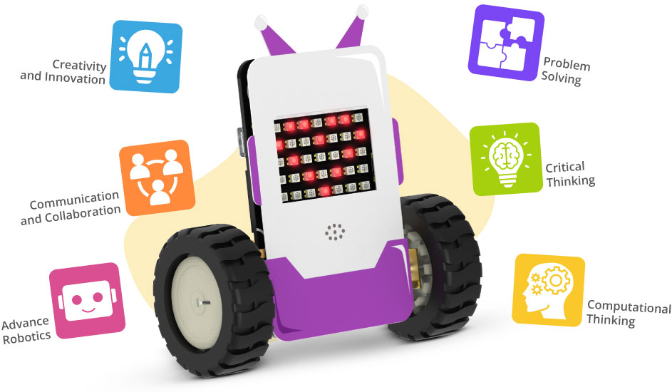
Absolutely no prior coding experience is required to use Quarky. It’s designed to be accessible to both beginners and those already familiar with coding. Quarky utilizes PictoBlox, a visual programming environment where projects are created through both block-based coding and Python. This interactive block-based coding interface simplifies the learning process and makes it enjoyable and highly engaging.
Absolutely! Quarky is designed for independent learning. Your child will have access to free, online, self-paced courses covering assembly, the logic behind how things work, and step-by-step coding. These resources make learning AI, Machine Learning, and Robotics engaging and easy through hands-on DIY projects. A helpful “Get Started” booklet is also included in the kit to jumpstart the learning process. Furthermore, upon course completion, your child will receive a certificate celebrating their achievements. This means Quarky includes everything needed for a child to learn effectively on their own, without requiring additional support or resources.
![]()
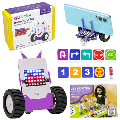
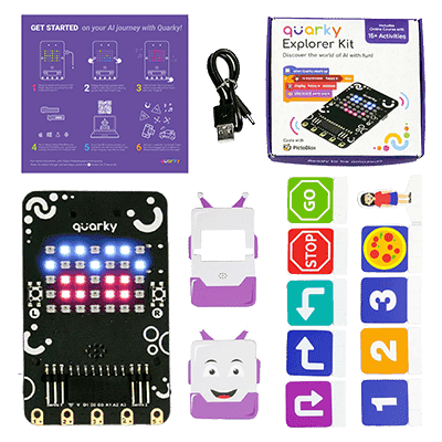
Quarky comes with built-in input and output devices:
10.1 Input: Touch sensors, tactile switches (buttons), IR sensors
10.2 Output: 7×5 RGB LED display, speaker, N20 motors, Geek Servo motor
10.3 Additional ports: 6 generic I/O ports and 2 servo motor ports
10.4 These devices allow you to create and control various fun and interactive robotics and AI projects!
Once the Quarky battery (1000 mAh) is fully charged, it can run for up to 4 hours and 49 minutes continuously. This includes using 4 DC motors, 2 servo motors, the 7×5 RGB LED display, and Bluetooth.
You can also check the Quarky Battery Testing Video here!
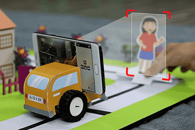
The kit includes a set of recognition cards that can be utilized in a wide range of activities involving Quarky. These cards enable functionalities such as self-driving cars, autonomous delivery bots, traffic signal detectors, and more. They serve as valuable tools for engaging and exploring different applications with Quarky. Know more
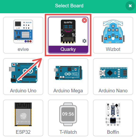
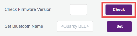
Please follow the instructions to check the Quarky Firmware version.
13.1 Connect your Quarky to the PictoBlox.
13.2 Go to the Quarky palette and click on the setting icon as shown below in the image
![]()
13.3 In the Quarky settings, click on the Check button to check the firmware version.
Quarky uses Bluetooth Low Energy (BLE) for wireless communication. The range depends on environmental factors:
14.1 Indoors: Up to 10 meters (may vary due to walls and interference).
14.2 Outdoors/Open Space: Up to 30 meters under ideal conditions.
14.3 For best performance, ensure there are minimal obstacles and interference from other wireless devices.
Currently, Quarky only supports a selection of built-in audio tunes. However, support for playing your own custom audio files is planned for a future release. We’ll keep you posted on the availability of this feature!
Indeed, Quarky offers Wi-Fi connectivity. This feature enables users to develop Internet of Things projects, encompassing functionalities like data logging, remote operation, and integration with cloud platforms.
To use Wi-Fi features with Quarky in PictoBlox:
17.1 First, add the IoT extension from the Extensions menu.
17.2 Ensure you are in Upload Mode. Wi-Fi related blocks are exclusively available when the code is uploaded directly to Quarky.
Yes, Quarky supports both Stage Mode and Upload Mode:
18.1 Stage Mode: Quarky responds in real-time when you run commands or programs directly from PictoBlox.
18.2 Upload Mode: You can create a program and upload it to Quarky using a USB cable. Once uploaded, Quarky will automatically execute the code every time it is powered on.
Quarky provides flexible coding options to suit different skill levels:
19.2 For beginners, there’s an intuitive block-based coding environment.
19.2 For more experienced users, Python programming is available.
For support regarding Quarky issues, please contact STEMpedia Support using the following:
Email: support@thestempedia.com
All Quarky functions, along with their corresponding Block and Python syntax, are detailed on the official STEMpedia Extension page: https://ai.thestempedia.com/extension/
Follow these quick steps:
Troubleshooting Steps:
You can use any of the following Bluetooth adapters, as they are compatible with Quarky:
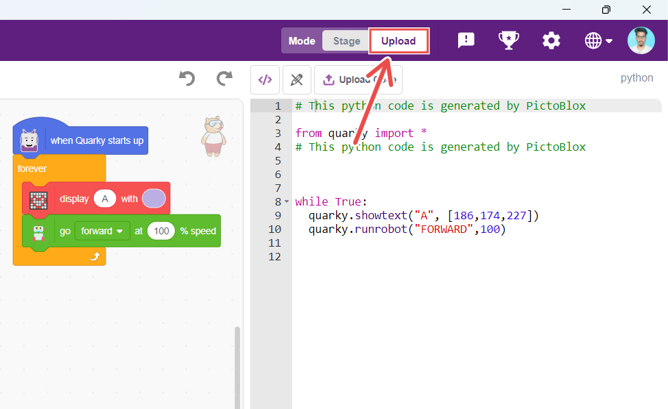
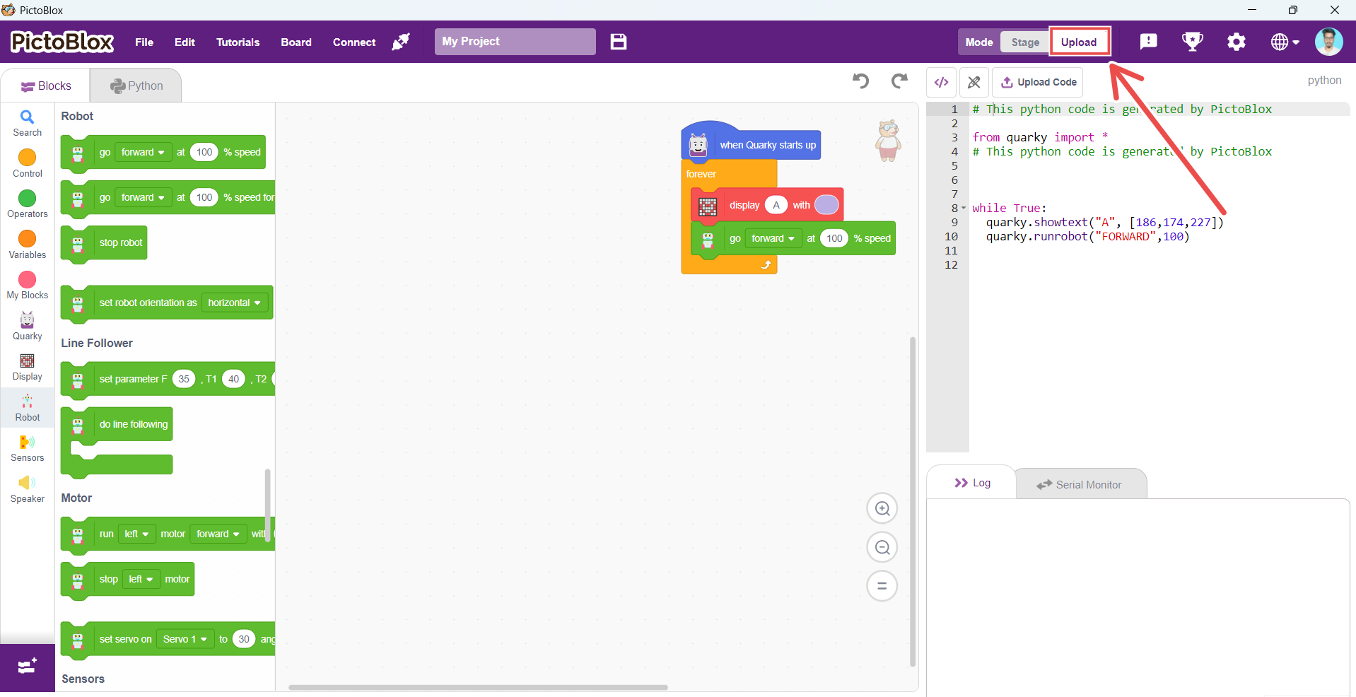
Firmware is required to run Quarky in Stage Mode. To upload the firmware, simply click the “Upload Firmware” button above the Stage in PictoBlox.
Try these steps:
You can connect Quarky using one of two methods:
1. Serial Port (USB)
1.1 Use a USB Type-C cable to connect Quarky to your PC.
1.2 Open PictoBlox and select the Quarky board.
1.3 Click the Connect tab next to the Board menu and choose the Serial Port.
2. Bluetooth Port
2.1 Make sure Bluetooth is enabled on your PC.
2.2 Ensure PictoBlox Link is installed and running.
2.3 Click the Connect tab and select the Bluetooth option.
Locate the reset button above the charging port on the back of Quarky.
1. Press and release the button:
1.1 In Stage Mode: Stops code execution and disconnects Bluetooth from PictoBlox.
1.2 In Upload Mode: Restarts the uploaded code from the beginning.
2. You can also upload the firmware via PictoBlox to fully reset Quarky. This will:
2.1 Erase any uploaded code
2.2 Restore default settings
3. Make Quarky ready for Stage Mode
Don’t worry! If Quarky isn’t responding, just upload the firmware again. It’s like giving Quarky a quick reboot to help it get back on track.
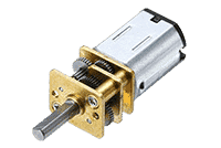
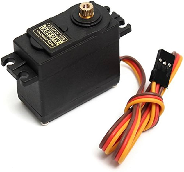
Quarky supports 3.7V and 5V motors, including:
1. N20 Motors
2. Geek Servo (180°)
3. Continuous rotation servo
4. Metal Servo Motor
Quarky works with 3.7V Li-ion batteries. For regular use, a 500mAh to 1000mAh battery is enough. For Quarky Addon Robots, it’s best to use a 1500mAh battery for longer use and better performance. Make sure the battery has a compatible JST connector to connect properly.